Scale for rotary encoder, method of injection-molding same, and rotary encoder using same

A technology of rotary encoder and scale, which is applied in the direction of converting sensor output, instrument, measuring device, etc., can solve the problems of difficulty in improving the resolution of the rotary encoder, difficulty in maintaining the accuracy of the flash mold, difficulty in maintaining the performance of the rotary encoder, etc., to achieve maintaining Accuracy, suppression of variation in performance between products, and effect of widening the irradiation range

Active Publication Date: 2014-03-05
KODENSHI +1
View PDF5 Cites 5 Cited by
  • Summary
  • Abstract
  • Description
  • Claims
  • Application Information

AI Technical Summary

Problems solved by technology

For example, if flash occurs when forming the light-shielding portion, the amount of light that can pass through the light-transmitting portion will change from the design value, or, due to the change in the amount of light that can pass through each light-transmitting portion, the performance of the rotary encoder will appear. Problems that are difficult to stabilize on every product
[0006] Moreover, the mold used for the resin molding scale is deteriorated due to passivation of the edge portion near the light-shielding portion or the light-transmitting portion during the repeated injection molding process.
When the die is degraded, such as passivation, it is easy to generate new burrs that did not occur in the initial stage of manufacturing, or the light-shielding part will be formed larger than the design, so the amount of light that can pass through the light-transmitting part will deviate from the design value, making it more difficult to maintain resolution Etc performance
[0007] In this way, in the case of a cylindrical scale, since the shape of the scale is more complex than that of a flat scale, the above-mentioned problem of burrs and the problem of difficulty in maintaining accuracy caused by the deterioration of the mold are likely to occur. The performance-related deviation problem, and the problem that the resolution of the rotary encoder itself is difficult to improve

Method used


Image

  • Scale for rotary encoder, method of injection-molding same, and rotary encoder using same
  • Scale for rotary encoder, method of injection-molding same, and rotary encoder using same
  • Scale for rotary encoder, method of injection-molding same, and rotary encoder using same

Examples


Embodiment Construction

[0054] One embodiment of the present invention will be described with reference to the drawings.

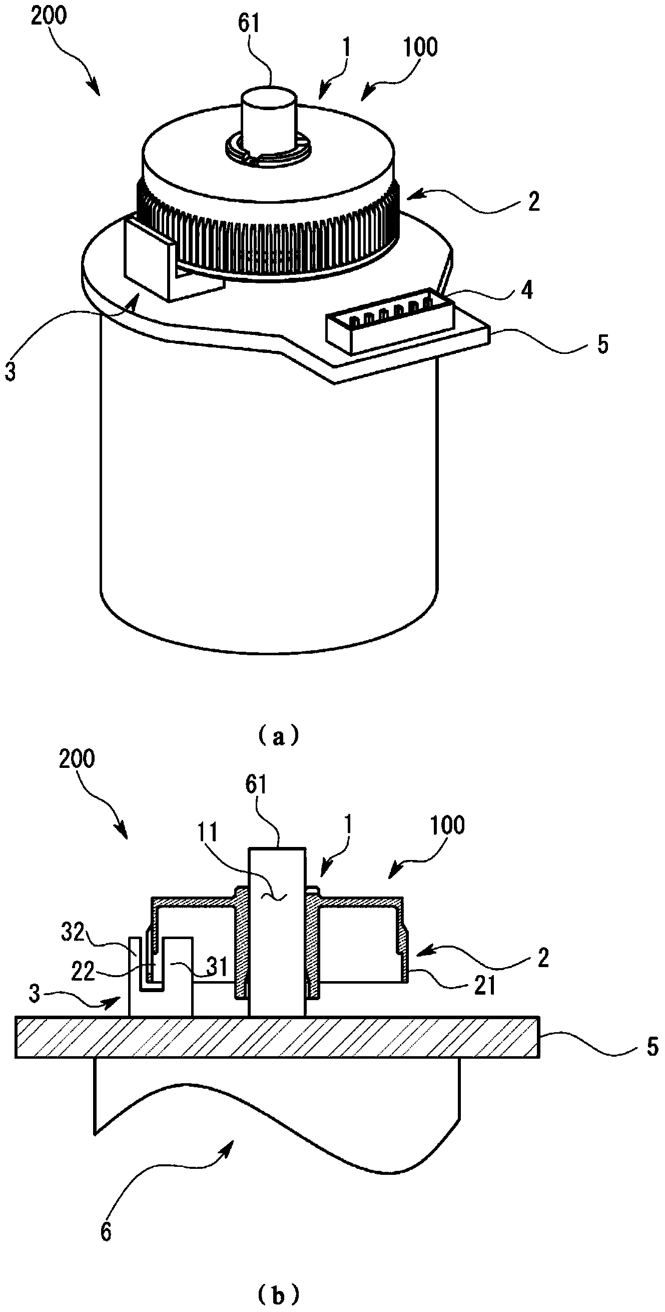
[0055] The rotary encoder scale 100 and the rotary encoder 200 of this embodiment are used, for example, to detect the rotation angle of small motors 6 such as printers and home appliances, and are particularly suitable for devices that house various devices and have a limited volume.

[0056] figure 1 The perspective view of (a) shows the state in which the rotary encoder 200 is attached to the small motor 6 . The rotary encoder scale 100 is generally flat cylindrical with an open bottom, the upper surface is fitted to the output shaft of the motor 6 , and the bottom is attached so as to face the main body of the motor 6 . In addition, the entire scale 100 for a rotary encoder is formed of resin. And, if figure 1 As shown in the perspective view of (a), a wiring substrate 5 for wiring is installed between the scale 100 and the main body of the motor 6, and the wiring substrat...


PUM


Abstract

For the purpose of reducing, in a radial optical path type rotary encoder made of resin, loss of resolution and variation of products due to burrs formed during molding and / or rounding of a die, a scale for a rotary encoder is provided with a scale body, which is formed substantially in a cylindrical shape or in a truncated conical shape and has a side part in which a light transmitting portion through which light passes and a light blocking portion by which light with a predetermined width in a circumferential direction is blocked are formed alternately in the circumferential direction, wherein the side surface of the light blocking portion on the light-incident side is formed outside a light transmittable region, an outer edge of which is defined by a light beam included in the light passing through the light transmitting portion, the light beam being tangent to the side surface of the light blocking portion, as viewed in the lateral cross-section.

Description

technical field [0001] The present invention relates to a scale used in a so-called radial type rotary encoder and an injection molding method thereof. Background technique [0002] As a rotary encoder for detecting the rotation angle of the motor, there is an axial optical path type rotary encoder in which a flat plate-shaped scale is fitted to the rotary shaft, and the optical path between the light source and the photodetector is set at In the same direction as the rotation shaft; and the radial optical path type rotary encoder is formed in a substantially cylindrical shape, and a so-called cylindrical scale having a slit formed on the side surface is fitted to the rotation shaft, and the optical path is set in the radial direction. [0003] For example, in a small motor used in a household printer or the like, it is necessary to reduce the volume required for installing a rotary encoder in the small motor as much as possible. In such applications, Patent Document 1 and...

Claims


Application Information

Patent Timeline
Patent Type & Authority Applications(China)
IPC IPC(8): G01D5/347
CPCG01D5/3473G01D5/34707
Inventor 福田英二砂田卓哉
Owner KODENSHI
Why Eureka
Try Eureka