
Method for assembling and device for assembling roller bearing

A technology of roller bearing and assembling device, applied in the field of roller bearing, can solve the problems of rolling surface damage of rollers and the like

Inactive Publication Date: 2014-03-05
NSK LTD
View PDF6 Cites 16 Cited by
  • Summary
  • Abstract
  • Description
  • Claims
  • Application Information

AI Technical Summary

Problems solved by technology

However, this assembly device has the same problem in that the rollers may be bitten between the outer peripheral surface of the central shaft and the inner peripheral surface of the housing, thereby causing damage to the rolling surfaces of the rollers.

Method used


Image

  • Method for assembling and device for assembling roller bearing
  • Method for assembling and device for assembling roller bearing
  • Method for assembling and device for assembling roller bearing

Examples


Embodiment Construction

[0038] [First example of embodiment]

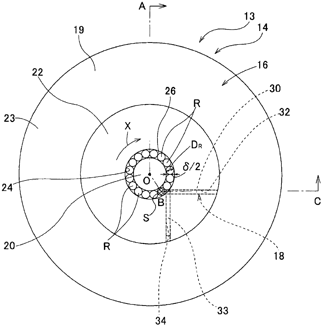
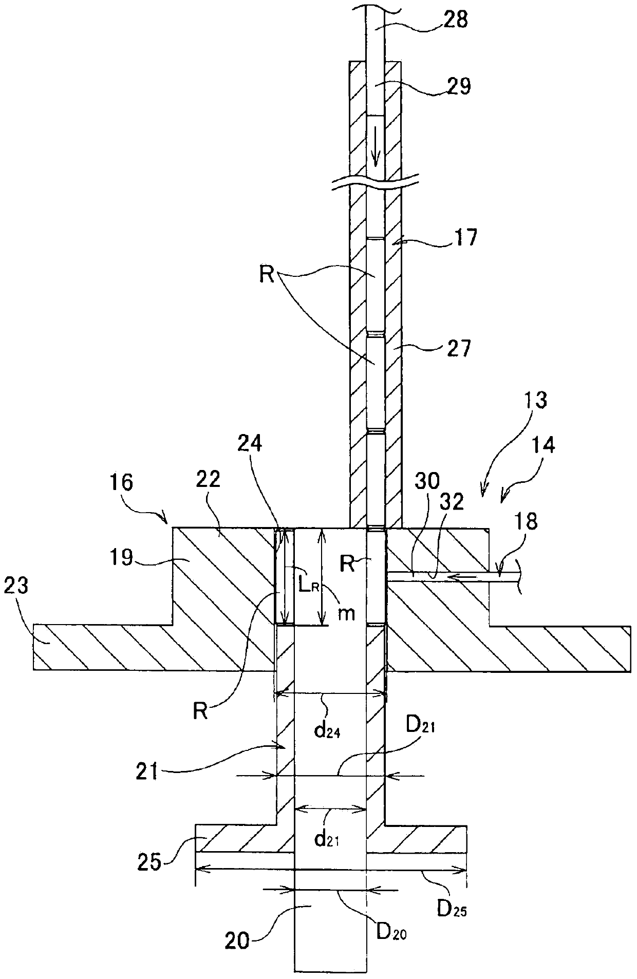
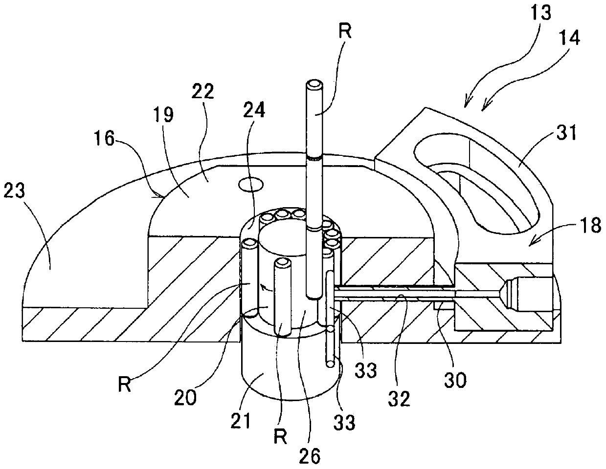
[0039] Figure 1 to Figure 8 The first example of the embodiment of the present invention is shown. The assembly device 13 is constituted by an alignment jig 14 and an insertion jig 15 for incorporating a plurality of rollers R inside an outer ring W constituting a full-roller type radial roller bearing.

[0040] The alignment jig 14 of the present invention includes a jig body 16 , a roller supply member 17 , and an alignment fluid supply member 18 . The jig main body 16 is composed of a guide cylinder 19, a guide shaft 20, an ejection jig 21, and a cover (not shown), and a predetermined spatial shape is formed in a part surrounded by these components so that a plurality of rollers can be arranged in parallel with each other. The permutation space of 26.

[0041] The guide cylinder 19 has a stepped cylindrical shape and is composed of a thick portion 22 at the inner diameter side half and a thinner portion 23 at the outer diameter sid...


PUM


Abstract

When assembling a roller bearing, the present invention effectively prevents rollers (R) assembled to the inside of an outer race (W) from tilting or dropping out from the state immediately after assembly. After arranging the rollers (R) in an annular shape by means of an arrangement jig (14), the roller group (G) arranged in an annular shape is ejected from the arrangement space (26) of the arrangement jig (14), and is pressed into a guide hole (39) of an insertion jig (15). As a result, in the state of inhibiting the diameter of the roller group (G) from widening by means of the inner peripheral surface of the guide hole (39), a holding member (36) made from an elastic material is inserted within the roller group (G) in the state of the holding member (36) being elastically compressed in diameter. Thereafter, an ejection tube (38) configuring the insertion jig (15) is displaced in the axial direction, simultaneously ejecting the roller group (G) and the holding member (36) from the guide hole (39), simultaneously assembling same within the outer race (W).

Description

technical field [0001] The present invention relates to a roller bearing assembly device and an assembly method used for assembling a roller bearing having a plurality of rollers, particularly a full-roller type radial roller bearing. Background technique [0002] Radial roller bearings are installed in the rotation support part for supporting a large radial load while supporting the rotating shaft. When it is necessary for the rotation support portion to support a larger radial load, a so-called full-roller type radial roller bearing in which the load capacity is increased is used without providing a cage. [0003] To assemble full-roller radial roller bearings, various assembly devices and jigs have conventionally been used. Figure 11 It shows the assembly apparatus of the conventional structure described in Unexamined-Japanese-Patent No. 5-329721. The assembly device 1 is composed of an alignment guide member 2, a guide rod 3, a push-in cylinder 4, a roller supply membe...

Claims


Application Information

Patent Timeline
IPC IPC(8): B23P21/00B23P19/00F16C19/26F16C43/06
CPCB23P21/00F16C43/06F16C19/26B23P19/04B23P19/00B23P19/001F16C19/46Y10T29/49679Y10T29/49682Y10T29/53104B23P19/10
Inventor 长崎雄一
Owner NSK LTD
Learn More