
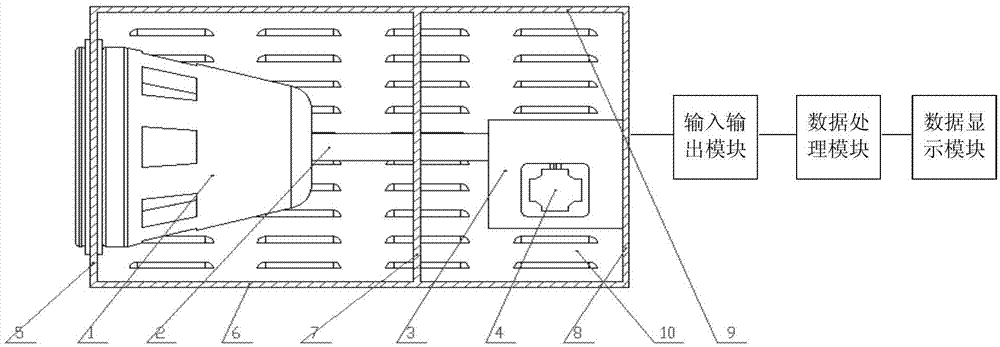
Light spot thermal flux density distribution test system

A technology for heat flux density and distribution testing, applied in calorimeters, measuring devices, measuring heat, etc., can solve problems such as working fluid leakage, explosion, and reliable testing of heat flux distribution rules without spots, so as to avoid burning and ensure safe operation Effect

Inactive Publication Date: 2014-03-05
XIANGTAN ELECTRIC MFG
View PDF4 Cites 7 Cited by
  • Summary
  • Abstract
  • Description
  • Claims
  • Application Information

AI Technical Summary

Problems solved by technology

Once the spot heat flux distribution is uneven due to the concentrating device, it will cause the hot end part of the heat absorber to heat up too quickly and melt down, and even cause the working fluid to leak or explode, causing serious consequences. The spot heat flux density distribution has high requirements
However, in the prior art, there is no device that can reliably test the distribution law of the spot heat flux

Method used


Image

  • Light spot thermal flux density distribution test system
  • Light spot thermal flux density distribution test system
  • Light spot thermal flux density distribution test system

Examples


Embodiment Construction

[0036] The following will clearly and completely describe the technical solutions in the embodiments of the application with reference to the drawings in the embodiments of the application. Apparently, the described embodiments are only some of the embodiments of the application, not all of them. Based on the embodiments in this application, all other embodiments obtained by persons of ordinary skill in the art without creative efforts fall within the protection scope of this application.

[0037] The core of this application is to provide a light spot heat flux distribution test system, the test system tests the light spot heat flux distribution generated by the concentrator system, and avoids heat sink heat caused by uneven distribution of light spot heat flux caused by concentrator system errors. End parts burn, and even cause leakage or explosion of working fluid, to ensure the safe operation of the power generation system.

[0038] figure 1 A light spot heat flux distrib...


PUM


Abstract

The invention discloses a light spot thermal flux density distribution test system. The light spot thermal flux density distribution test system comprises a ceramic installation base, a plurality of temperature sensors, an input and output module, a data processing module, a data display module, a rear end cover plate, a top plate, a bottom plate, a middle supporting plate, two side plates, a speed reducer and a drive motor, wherein one end of the ceramic installation base is fixed to the position of a circular hole in a front end cover plate, the other end of the ceramic installation base is connected with a rotating shaft, the temperature sensors are distributed on the test installation face of the ceramic installation base, the rear end cover plate is provided with the speed reducer, a circular hole used for allowing the rotating shaft to penetrate through is formed in the middle of the middle supporting plate, the other end of the rotating shaft is connected with the speed reducer, the drive motor is arranged on the speed reducer, the drive motor drives the speed reducer to rotate, and rotation is delivered to the rotating shaft so that the ceramic installation base can be driven to rotate. The light spot thermal flux density distribution test system can test whether the thermal flux density distribution of light spots on a whole section is even or not, and the phenomenon that when light spot thermal flux density distribution is not even due to condenser system errors, a hot end part of a thermal absorber is burnt, and even a working medium leaks or explodes is avoided.

Description

technical field [0001] The present application relates to the technical field of dish solar power generation systems, and more specifically, to a spot heat flux distribution testing system. Background technique [0002] The utilization of solar thermal power generation has more and more important social and economic significance. An important technology used in solar thermal power generation is the dish system, which gathers solar energy through a dish concentrator, then converts it into thermal energy, and then converts it into mechanical energy by a heat engine, and then converts it into electrical energy through a motor. This method has very flexible modular deployment capabilities, high light-to-heat conversion efficiency, and high utilization factor, so it has attracted attention and attention. [0003] As a key component of the dish solar power generation system, the heat absorber is to absorb the solar energy gathered by the concentrating device and convert it into h...

Claims


Application Information

Patent Timeline
IPC IPC(8): G01K17/00
Inventor 黄剑锋刘红谭新华党安旺黄敏
Owner XIANGTAN ELECTRIC MFG
Learn More