Pore plate with ablative function and pipeline system
An orifice plate and function technology, which is applied in the improvement field of throttling orifice plate to eliminate cavitation, can solve the problems of deteriorating working environment, pipeline fatigue damage, single-stage orifice plate cannot achieve stable throttling, etc. Apply flexible effects
- Summary
- Abstract
- Description
- Claims
- Application Information
AI Technical Summary
Problems solved by technology
Method used
Image
Examples
Embodiment 1
[0025] Such as Figure 1 to Figure 3 shown.
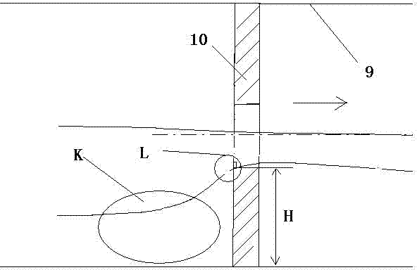
[0026] Such as figure 1 is a schematic diagram of a conventional single-hole throttle orifice 10 . The arrows in the figure indicate the flow direction of the fluid, and the area L is the upstream end surface of the traditional single-hole throttle orifice 10 , which affects the resistance characteristics of the traditional single-hole throttle orifice 10 . After testing, it is found that even a small arc there will greatly reduce the resistance characteristics of the throttle orifice. Therefore, the shape at L is maintained at 90°, that is, when the inner diameter surface of the flow hole of the traditional single-hole throttling orifice 10 is perpendicular to the upstream end face of the traditional single-hole throttling orifice 10, the resistance coefficient is the best. However, if the L point is at a right angle, the fluid flowing from the K area will easily form a boundary shedding at the L point, forming a negative press...
Embodiment 2
[0031] The difference between this embodiment and embodiment 1 is:
[0032] Preferably, the thickness of the ring body is the length of the right-angled side M, the thickness of the ring body is Q, and the thickness of the ring body satisfies the relational formula: Q is 30%H-80%H, and H is the radius of the flowing water orifice body 2 and the flowing water The difference between the radii of the holes 21.
[0033] After comparison and measurement, it shows that the cavitation generated by the pipeline installed with the flow orifice plate is significantly smaller than that of the conventional orifice plate, and the vibration of the pipeline is greatly reduced. figure 1 The structure, the air-to-noise ratio of the same point of the scene of this embodiment figure 1 The air noise at the same point on the site of the structure is less than 15dB. The visual observation effect behind the orifice plate shows that the vaporization phenomenon behind the orifice plate has been grea...
Embodiment 3
[0035] The difference between this embodiment and embodiment 1 is:
[0036] The thickness of the ring body is the length of the right-angled side M, the thickness of the ring body is Q, and the thickness of the ring body satisfies the relational formula: Q is 40%H-70%H, and H is the radius of the water orifice plate body 2 and the diameter of the water hole 21 difference in radius.
[0037] After comparison and measurement, it shows that the cavitation generated by the pipeline installed with the flow orifice plate is significantly smaller than that of the conventional orifice plate, and the vibration of the pipeline is greatly reduced. figure 1 The structure, the air-to-noise ratio of the same point of the scene of this embodiment figure 1 The air noise at the same point of the structure is less than 20dB. The visual observation effect behind the orifice plate shows that the vaporization phenomenon behind the orifice plate has been greatly suppressed. The number of bubbles...
PUM
 Abstract
Description
Claims
Application Information
 - R&D
- Intellectual Property
- Life Sciences
- Materials
- Tech Scout
- Unparalleled Data Quality
- Higher Quality Content
- 60% Fewer Hallucinations
Browse by: Latest US Patents, China's latest patents, Technical Efficacy Thesaurus, Application Domain, Technology Topic, Popular Technical Reports.
© 2025 PatSnap. All rights reserved.Legal|Privacy policy|Modern Slavery Act Transparency Statement|Sitemap|About US| Contact US: help@patsnap.com


