Combined non-spill drain baffle

A leak-free, baffle technology, applied in liquid fuel engines, oscillating piston machinery, machines/engines, etc., can solve the problem of difficult to block gas backflow, low discharge pressure and volumetric efficiency of oscillating pumps, and limited application range of oscillating rotor pumps, etc. problem, to achieve the effect of enhanced impact resistance, convenient installation and maintenance, and reduced radial size

Inactive Publication Date: 2016-02-10
ZHEJIANG UNIV
View PDF5 Cites 0 Cited by
  • Summary
  • Abstract
  • Description
  • Claims
  • Application Information

AI Technical Summary

Problems solved by technology

[0004] In particular, in the process of gas-liquid mixed transportation, the gas leakage rate is much greater than the liquid leakage rate, and the existing structures of various swing rotor pumps are difficult to block the backflow of gas, resulting in the discharge pressure and volumetric efficiency of the swing pump. Both are low, which limits the application range of the swing rotor pump in conveying gas-liquid two-phase media

Method used


Image

  • Combined non-spill drain baffle
  • Combined non-spill drain baffle
  • Combined non-spill drain baffle

Examples


Embodiment 1

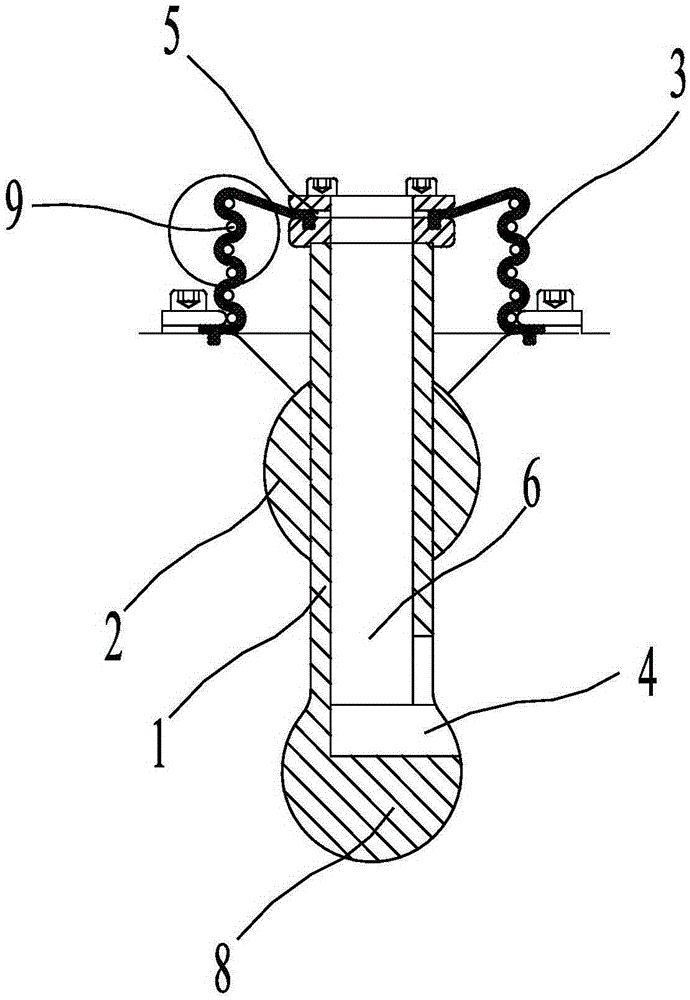
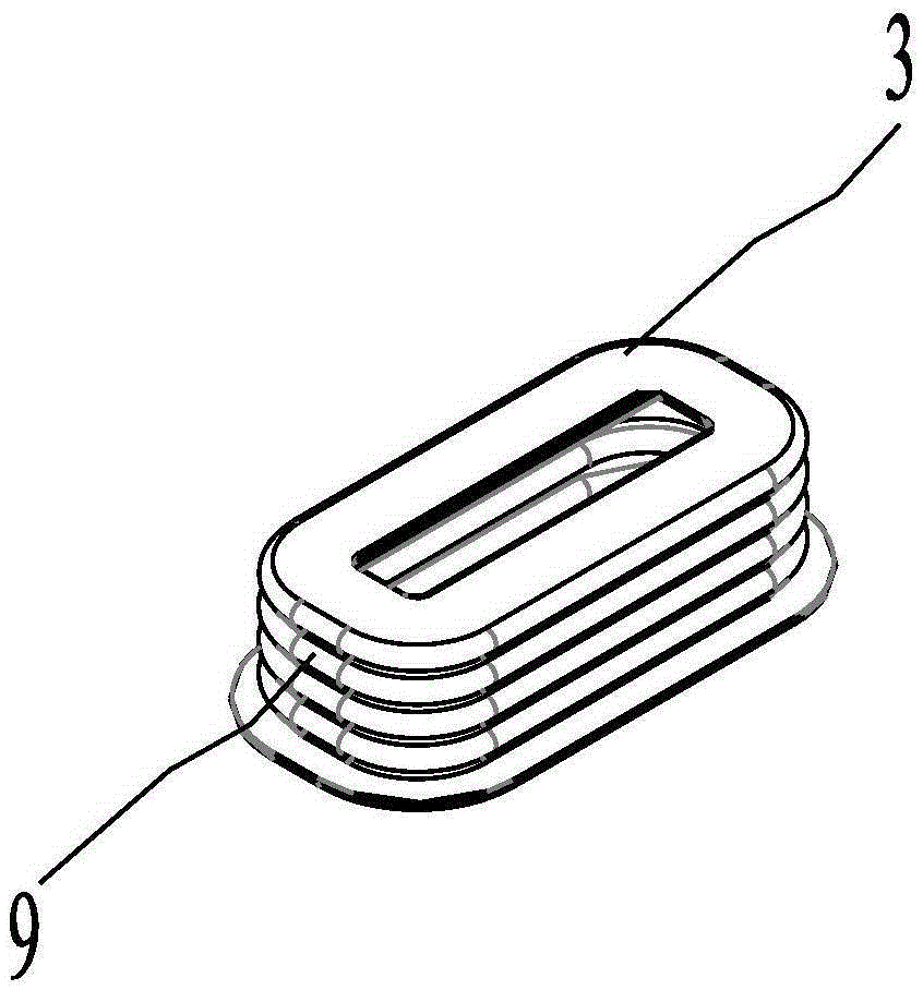
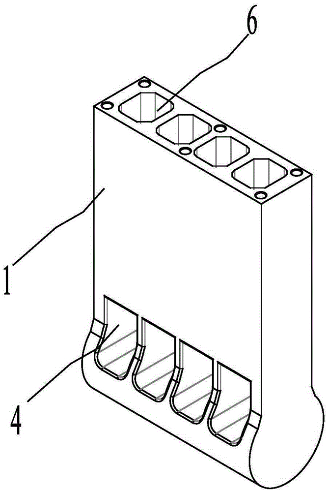
[0026] Embodiment 1, Figure 1 to Figure 4 A combined non-leakage drain partition is given, including the drain partition 1, the roller 2 and the rectangular diaphragm 3; the drain partition 1 is provided with a drain channel 6 (the number of the drain channel 6 can be determined according to the pump Choose the size of the pump, if the pump is large, you can set multiple discharge channels 6, if the pump is small, you can set at least one discharge channel 6), such as figure 2 As shown, in this embodiment, four drainage channels 6 are used, and reinforcing ribs 7 are provided between any adjacent two drainage channels 6. If the number of drainage channels 6 exceeds one, you can set Ribs 7 are used to ensure the rigidity of the drainage channel 6 . Corresponding cylindrical channel 8 is set at the lower end of the liquid discharge partition 1 (cylindrical channel 8 is set corresponding to the cylindrical groove of the swing pump rotor. Generally, the swing pump rotor has cyl...


PUM


Abstract

The invention discloses a combined no-leakage liquid discharging baffle. The combined no-leakage liquid discharging baffle comprises a liquid discharging baffle (1), a rolling column (2) and a rectangular diaphragm (3), wherein the rolling column (2) is sheathed on the liquid discharging baffle (1); the upper end of the liquid discharging baffle (1) is provided with the rectangular diaphragm (3).

Description

technical field [0001] The invention relates to a non-leakage liquid discharge partition, in particular to a combined non-leakage liquid discharge partition suitable for an eccentric translation non-contact rotor pump for gas-liquid mixed transportation. Background technique [0002] The eccentric translation non-contact rotor pump (swing rotor pump) is a fluid machine that can convert the mechanical energy of the prime mover into the pressure potential energy of the conveyed fluid. Function, the pump rotor and the pump casing form a volume that is separated from the pump outlet and communicated with the inlet. With the movement of the rotor, the volume gradually increases, and then the rotor reaches the point where a part of the volume is also isolated from the pump inlet. Finally, This volume is connected to the outlet of the pump, and the liquid in this volume is expelled under the movement of the rotor, mainly used in the application of multi-phase material delivery and ...

Claims


Application Information

Patent Timeline
IPC IPC(8): F04C9/00
Inventor 刘迎圆王乐勤朱祖超连加俤
Owner ZHEJIANG UNIV
Why Eureka
Try Eureka