
Prestress sectional steel reinforcing system of reinforced concrete arch shell bridge body

A reinforced concrete and arch-shell bridge technology, which is applied in bridge reinforcement, bridge, bridge construction, etc., can solve the problems of unloading, high cost, and large amount of engineering, and achieves a clear force, simple structure, and convenient construction. Effect

Active Publication Date: 2014-03-05
UNIJES GRP +1
View PDF8 Cites 9 Cited by
  • Summary
  • Abstract
  • Description
  • Claims
  • Application Information

AI Technical Summary

Problems solved by technology

In addition to the large amount of engineering and high cost of these methods, the main problem is that they cannot form a certain unloading effect on the excessive compressive stress of the original structure, and the post-reinforcement system cannot fully cooperate with the original structure.
The main reason is that the original arch slab (arch wave) is already in a high stress state before the new live load is applied, and the reinforcement system has not yet been stressed at this time, and it will participate in the joint force after the new live load is applied, so that The reinforcement effect of these methods is not good, and the purpose of significantly improving the bearing capacity of the original structure cannot be achieved.

Method used


Image

  • Prestress sectional steel reinforcing system of reinforced concrete arch shell bridge body
  • Prestress sectional steel reinforcing system of reinforced concrete arch shell bridge body
  • Prestress sectional steel reinforcing system of reinforced concrete arch shell bridge body

Examples


Embodiment Construction

[0028] The present invention will be further described below in conjunction with drawings and embodiments.

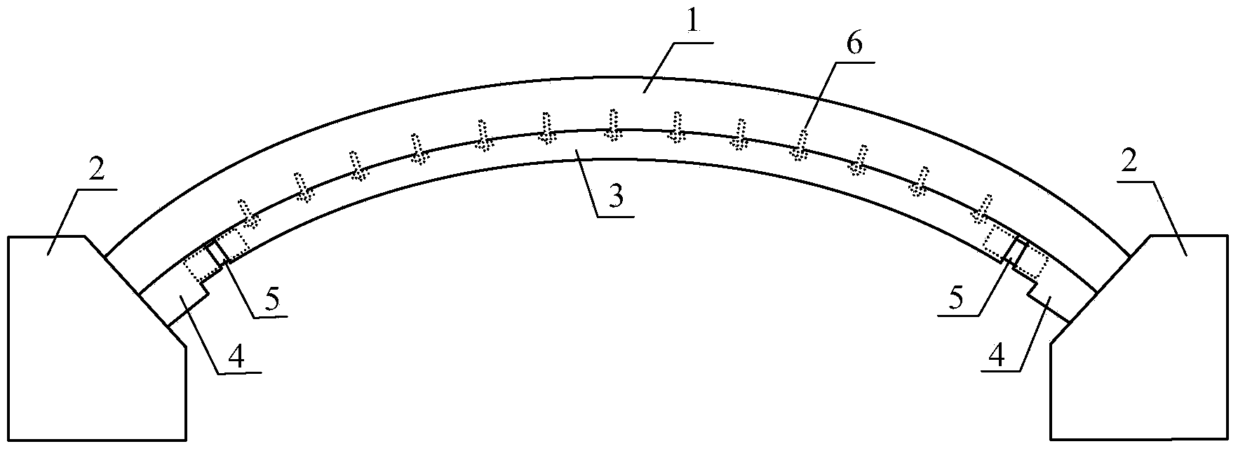
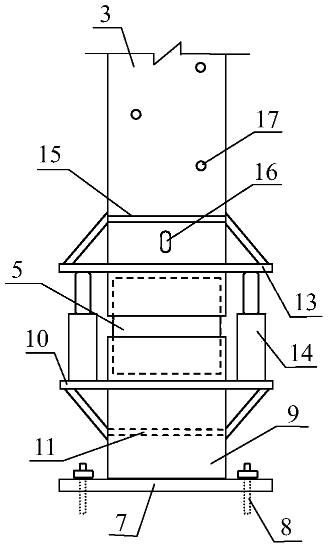
[0029] like Figure 1 ~ Figure 3 As shown, this embodiment includes longitudinal arched steel (channel steel) 3, steel support 4, and connecting steel sleeve 5. The steel support 4 includes a support base plate 7, a support steel body 9, a laterally extending corbel 10, and a top-extending section steel (channel steel) 12, and the support base plate is anchored with the concrete foundation 2 of the arch bridge with a bolt 8. The longitudinal shape of the longitudinal arch steel 3 is consistent with the longitudinal shape of the bottom of the reinforced arch shell 1. After it is in place, its top plate is in close contact with the reinforced arch shell, and the chemical bolt 6 is vertically connected to the arch shell at the elongated socket 16. Temporarily anchored laterally and laterally, but not fully anchored, allowing longitudinal movement. Corbels 13 protruding t...


PUM


Abstract

The invention relates to a prestress sectional steel reinforcing system of a reinforced concrete arch shell bridge body. The prestress sectional steel reinforcing system is composed of one or more pieces of longitudinal arch type steel, steel supports, connection steel sleeves and horizontal linkage sectional steel and arranged on the bottom face of an arch shell. After prestress is exerted at the two ends of the longitudinal arch type steel, the longitudinal arch type steel is welded to the steel supports at the end portions through the connection steel sleeves. A sectional steel top board is anchored with the arch shell through a chemical bolt. The horizontal linkage sectional steel is welded between the adjacent longitudinal sectional steel or between the longitudinal sectional steel and original edge arch ribs and anchored with the arch shell through a chemical bolt. According to the prestress sectional steel reinforcing system, the local detaching action on an original arch shell is achieved, and in addition, a reinforcing system and an original structure can fully and cooperatively work under the action of new and old loads. The prestress sectional steel reinforcing system is a longitudinal and horizontal rib beam bearing system which is relatively independent and participates in synergy, longitudinal and horizontal span of the original arch shell can be effectively reduced, and the bearing capability of the arch shell can be obviously improved. The prestress sectional steel reinforcing system is simple in structure, definite in stress and easy and convenient to construct and does not cause obvious influences on the traffic on a bridge, the ambient environment and the like.

Description

technical field [0001] The invention relates to the field of bridge and structural engineering in the discipline of civil engineering, in particular to a prestressed section steel reinforcement system for a reinforced concrete arch shell bridge body. Background technique [0002] Reinforced concrete arch bridges without ribs and wide arch bridges with few ribs (such as two ribs and single waves) arch bridges are commonly used bridge structures in engineering. Most of the arch slabs (or arch waves) of this type of bridge are designed as double-curved double-curved surfaces, and under the action of vertical loads, they are often in a state of stress mainly under compression and combined with bending and shearing. In my country, most of this type of arch bridges were built in the 1960s to 1980s. With the continuous increase of traffic volume, the arch slabs or arch waves of these bridges are often in an overloaded operation state, resulting in insufficient bearing capacity suc...

Claims


Application Information

Patent Timeline
IPC IPC(8): E01D22/00
Inventor 沈安跃毛义华孙宏磊吴焕东孙飞李洪宇韩秉玺
Owner UNIJES GRP
Learn More