
Split-phase excitation power topological structure of switched reluctance motor

A switched reluctance motor, excitation power technology, applied in the direction of electronic commutation motor control, electrical components, control systems, etc., can solve the problems of low system work efficiency, short freewheeling time, etc., to shorten the freewheeling time and reduce the continuous flow. The effect of flow time and improving system efficiency

Inactive Publication Date: 2014-02-26
HARBIN INST OF TECH
View PDF3 Cites 13 Cited by
  • Summary
  • Abstract
  • Description
  • Claims
  • Application Information

AI Technical Summary

Problems solved by technology

[0003] The purpose of the present invention is to solve the problems that the energy of each phase winding of the drive power structure of the existing switched reluctance motor is fed back to the power supply when the freewheeling is turned off, the power supply voltage will not rise, the freewheeling time is short, and the system work efficiency is low. A split-phase excitation power topology for switched reluctance motor

Method used


Image

  • Split-phase excitation power topological structure of switched reluctance motor
  • Split-phase excitation power topological structure of switched reluctance motor
  • Split-phase excitation power topological structure of switched reluctance motor

Examples


specific Embodiment approach 1

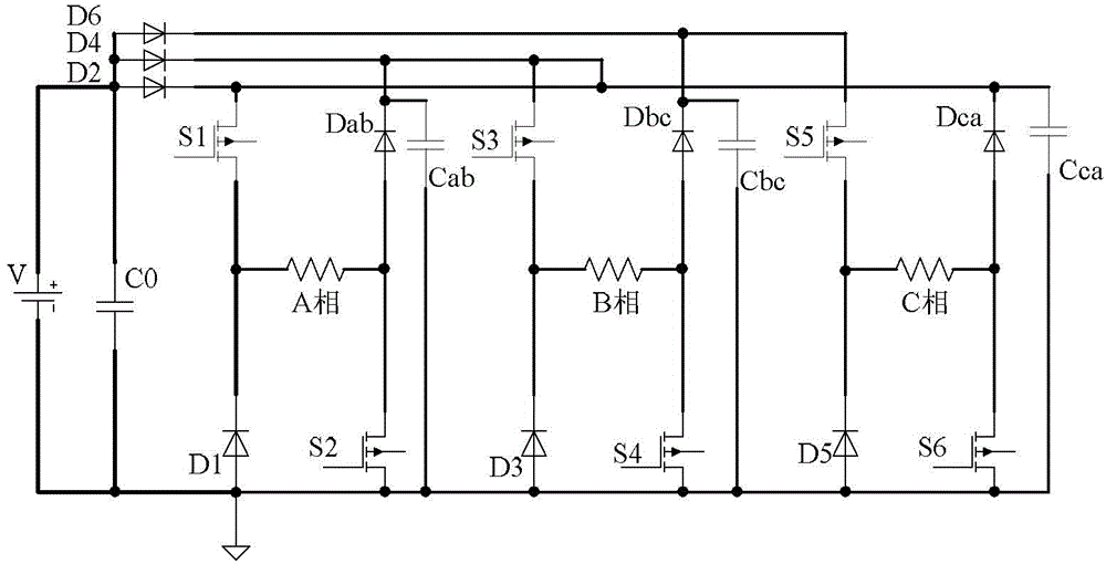
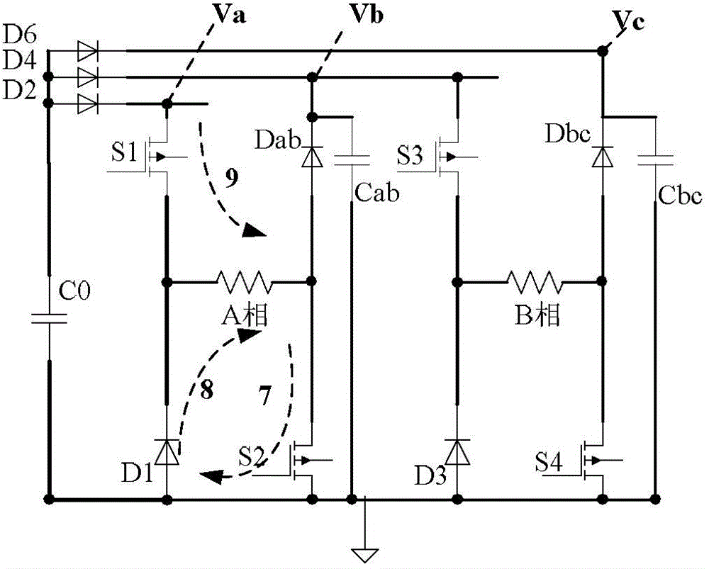
[0015] Specific implementation mode one: the following combination figure 2 Describe this embodiment, the shaft switched reluctance motor described in this embodiment has a phase-separated excitation power topology, which includes A-phase windings, B-phase windings, C-phase windings, power supply filter capacitor C0, and six switching tubes S1, S2, and S3 , S4, S5 and S6, six freewheeling diodes D1, D3, D5, Dab, Dbc and Dca;

[0016] The anode of the power supply V is simultaneously connected to the source of the switching tube S1, the cathode of the freewheeling diode Dab, the source of the switching tube S3, the cathode of the freewheeling diode Dbc, the source of the switching tube S5, and the cathode of the freewheeling diode Dca, to supply power The negative pole of the power supply V is simultaneously connected to the anode of the freewheeling diode D1, the drain of the switching tube S2, the anode of the freewheeling diode D3, the drain of the switching tube S4, the an...


PUM


Abstract

The invention provides a split-phase excitation power topological structure of a switched reluctance motor, and belongs to the field of motors. The structure aims to solve the problems that windings of each phase of an existing drive power structure of the switched reluctance motor feed back energy to a power supply in the free-wheeling switching off process, the voltage of the power supply does not rise, the free-wheeling time is short, and system work efficiency is low. The split-phase excitation power topological structure comprises an A-phase winding, a B-phase winding, a C-phase winding, a power supply filtering capacitor C0, a switching tube S1, a switching tube S2, a switching tube S3, a switching tube S4, a switching tube S5, a switching tube S6, a free-wheeling diode D1, a free-wheeling diode D3, a free-wheeling diode D5, a free-wheeling diode Dab, a free-wheeling diode Dbc, a free-wheeling diode Dca, an isolating anti-reflow diode D2, an isolating anti-reflow diode D4, an isolating anti-reflow diode D6, an A-phase winding bus capacitor Cca, a B-phase winding bus capacitor Cab and a C-phase winding bus capacitor Cbc. The switching tubes from S1 to S6 are identical in structure. The split-phase excitation power topological structure is used for the switched reluctance motor.

Description

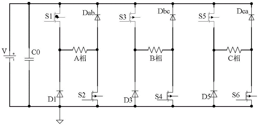
technical field [0001] The invention relates to a phase-separated excitation power topology structure of a switched reluctance motor, belonging to the field of motors. Background technique [0002] The existing switched reluctance motor drive semi-symmetrical power circuit such as figure 1 As shown, each phase winding uses two main switches and two slow-flow diodes. When the two main switches S1 and S2 are turned on, the winding is connected to the DC power supply to form a current; when S1 and S2 are turned off, the current flows through D1—the A phase winding—Dab. The bus bars of each phase winding are connected together, and the voltage is equal to the power supply voltage V; when the freewheeling current of each phase winding is turned off, the energy is directly fed back to the power supply, and the power supply voltage will not rise. Contents of the invention [0003] The purpose of the present invention is to solve the problems that the energy of each phase windin...

Claims


Application Information

Patent Timeline
IPC IPC(8): H02P6/00
Inventor 吴红星黄玉平仲悦郑再平杨旭强
Owner HARBIN INST OF TECH
Learn More