
Non-refrigeration detector forest fire prevention system

A forest fire prevention and detector technology, which is applied in the direction of instruments, alarms, and fire alarms that rely on radiation effects, can solve the problems of inability to distinguish the morphological characteristics of clouds and forest fires in forest areas, the inability to determine fire alarm points in time, and the cost of the system High-level problems, to achieve low-cost real-time monitoring, improve professional capabilities, and high detection sensitivity

Inactive Publication Date: 2014-02-26
CHENGDU JINGLIN ELECTRONICS TECH
View PDF4 Cites 1 Cited by
  • Summary
  • Abstract
  • Description
  • Claims
  • Application Information

AI Technical Summary

Problems solved by technology

[0011] In order to overcome the existing technology in the monitoring of forest fire prevention, a large number of cameras need to be deployed in the forest area, and the system cost is high. These cameras can only work in the case of better light, and cannot work at night or even in the case of low daytime illumination ;In the image analysis system of the monitoring center, it is impossible to distinguish the morphological characteristics of the cloud and fog in the forest area from the forest fire. Usually, manual identification and early warning are used. When a fire occurs, the fire alarm point cannot be determined in time, and the technology of understanding the geographical conditions of the fire alarm point Deficiency, the present invention provides non-refrigerated detector forest fire prevention system

Method used


Image

  • Non-refrigeration detector forest fire prevention system
  • Non-refrigeration detector forest fire prevention system

Examples


Embodiment 1

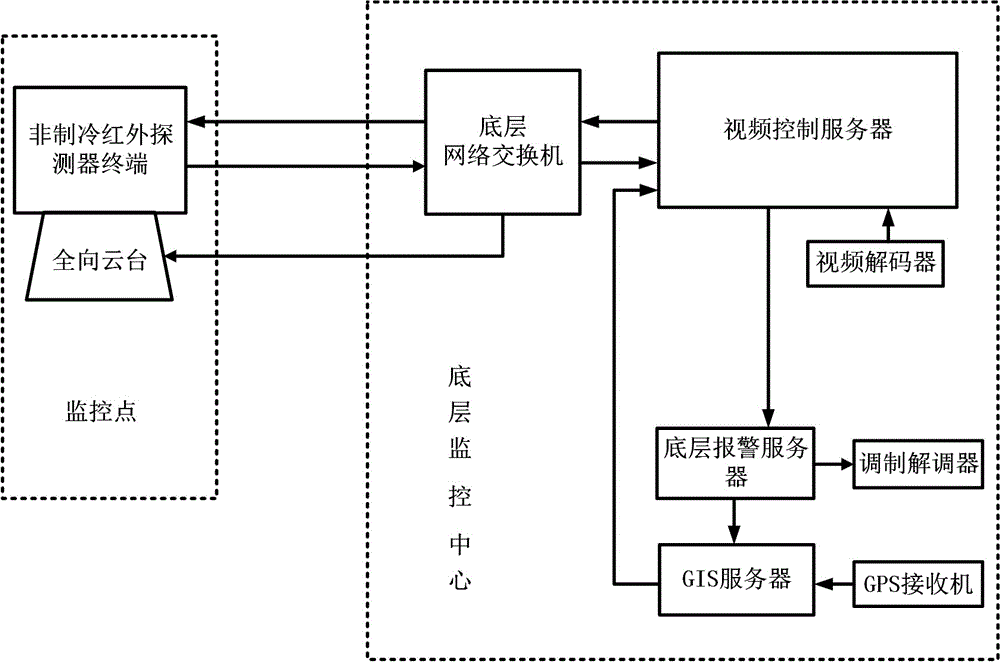
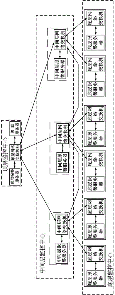
[0036] Such as figure 1 As shown, the present invention comprises the bottom monitoring center and a plurality of monitoring points that are arranged on forest area, is characterized in that: described bottom monitoring center is provided with bottom alarm server, GIS server, GPS receiver, video control server, video decoder , an alarm, a bottom network switch, the monitoring point is provided with an omnidirectional pan / tilt, an uncooled infrared detector terminal, the uncooled infrared detector terminal is installed on the omnidirectional pan / tilt, and the uncooled infrared detector terminal Connect the underlying network switch through a wired or wireless network, the underlying network switch is connected to the video control server, the video control server is connected to the video decoder, the video control server is connected to the bottom layer alarm server, and the bottom layer alarm server is connected to the GIS server. The GIS server is connected to the video cont...

Embodiment 2

[0039] In order to improve the adaptability of the uncooled detector forest fire prevention system at the monitoring point, this embodiment is further improved on the basis of Embodiment 1. The uncooled infrared detector terminal of this embodiment includes an uncooled infrared temperature detector, a video encoding The uncooled infrared temperature detector is connected to the video encoder, and the uncooled infrared detector terminal is connected to the underlying network switch through a wired or wireless network.

[0040] The specific data of the components of the present invention are: the uncooled infrared detector terminal including the uncooled infrared temperature detector adopts the U6000 type of DRS company, the specific parameters are 640×480 FPA, the pixel size is 25.4 μm, and the wavelength is 8-12 μm; the video encoder adopts Texas Instruments' TMS320DM6467T chip, the video output format is H.264, MPGE-4 / 2.

[0041] Those skilled in the art can freely select the...

Embodiment 3

[0043] In order to improve the ability of the uncooled detector forest fire prevention system to obtain fire alarm video data at the monitoring point, this embodiment makes the following improvements on the basis of Embodiment 2. The uncooled detector forest fire prevention system of this embodiment is characterized in that: The uncooled infrared temperature detector includes a thermoelectric cooler and a microbolometer array arranged on the thermoelectric cooler, the microbolometer array includes a plurality of thermosensitive elements arranged in a matrix In the focal plane of the uncooled infrared temperature detector.

[0044] The specific data of the components of the present invention are: the microbolometer array adopts the UL03191 amorphous silicon microbolometer of ULIS Company, and its specific parameters are that the area of ​​the image sensing surface is 9.6mmx7.2mm, and the array format is 1000×1000 yuan. The pixel size is 25 μm×25 μm, and the maximum frame freque...


PUM


Abstract

The invention discloses a non-refrigeration detector forest fire prevention system. The system comprises a bottom-layer monitoring center and multiple monitoring points disposed in a forest area. The bottom-layer monitoring center is provided with a bottom-layer alarm server, a GIS server, a GPS receiver, a video control server, a video decoder, an alarm and a bottom-layer network switch; the monitoring points are provided with omnidirectional holders and non-refrigeration infrared detector terminals; the non-refrigeration infrared detector terminals are installed on the omnidirectional holders; the non-refrigeration infrared detector terminals are connected with the bottom-layer network switch through a network; the bottom-layer network switch is connected with the video control server; the video control server is connected with the video decoder and the bottom-layer alarm server; the bottom-layer alarm server is connected with the GIS server; the GIS server is connected with the video control server; the GPS receiver is connected with the GIS server; and the alarm is connected with the bottom-layer alarm server through the video control server. By using the system provided by the invention, forest fire prevention monitoring can be finally handled round the clock through the coordination of all departments in all regions.

Description

technical field [0001] The invention relates to the field of security technology, in particular to a forest fire monitoring system, more specifically a non-cooling detector forest fire prevention system. Background technique [0002] Forests have the functions of air purification, soil consolidation and water conservation, maintenance of ecological balance, and provision of production resources. In recent years, sandstorms have occurred frequently in our country, and desertification has continued to intensify, which is closely related to the destruction of forests. Every year, a certain number of forest fires occur around the world. Forest fires are characterized by suddenness, uncertainty, and huge damage in a short period of time. Large-scale forest fires are often caused by invisible hidden fires. [0003] At first, humans used to build watchtowers to warn forest fires manually. In this way, only large forest fires can be found; later, for forest areas with high forest ...

Claims


Application Information

Patent Timeline
IPC IPC(8): G08B17/12G08B25/00
Inventor 殷刚
Owner CHENGDU JINGLIN ELECTRONICS TECH
Learn More