
Air heating type fuel economizer

A technology of air heating and fuel economizer, which is applied in the direction of combustion air/combustion-air treatment, machine/engine, fuel heat treatment device, etc. It can solve the problems of incomplete combustion of gasoline, increased fuel consumption, and power drop, etc., and achieves inhibition of diffusion and loss, improve combustion efficiency, and intensify the effect of thermal movement

Inactive Publication Date: 2014-02-26
南宁明航节能科技有限公司
View PDF6 Cites 0 Cited by
  • Summary
  • Abstract
  • Description
  • Claims
  • Application Information

AI Technical Summary

Problems solved by technology

During the running of the car, since the engine needs to operate under various complex working conditions, it is difficult for the engine intake system to ensure sufficient mixing of air and gasoline, which will easily cause gasoline to be incompletely combusted, increase fuel consumption, increase exhaust gas, and reduce power
In the current market, there are also fuel economizers to control the air volume required by the engine under different working conditions or provide an oxygen-enriched environment for the combustion chamber, but most of the fuel economizers have complicated structures and are not convenient to attach to the car

Method used


Image

  • Air heating type fuel economizer
  • Air heating type fuel economizer
  • Air heating type fuel economizer

Examples


Embodiment

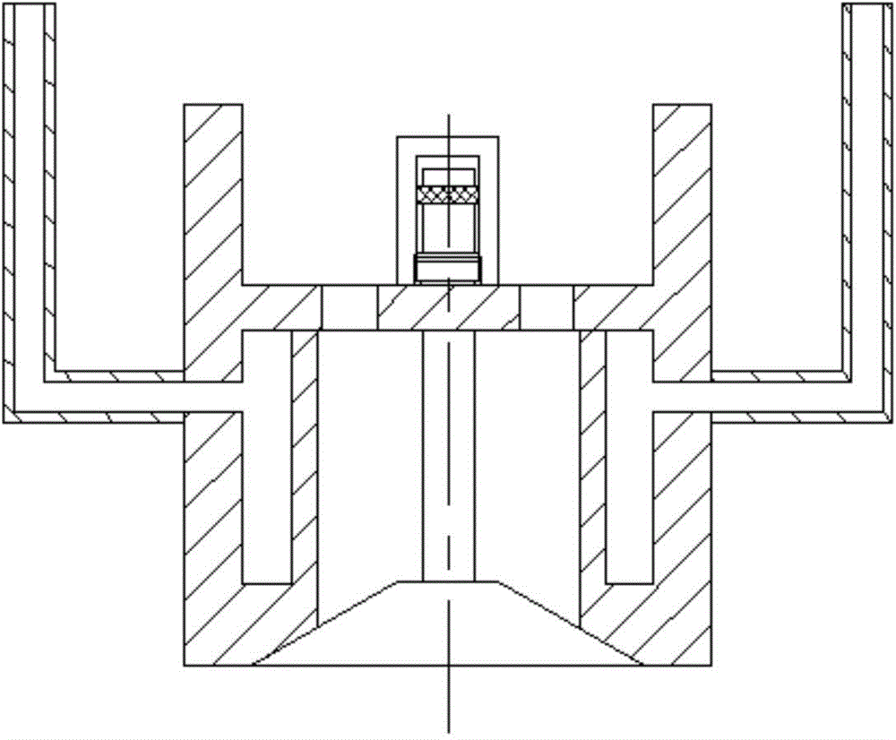
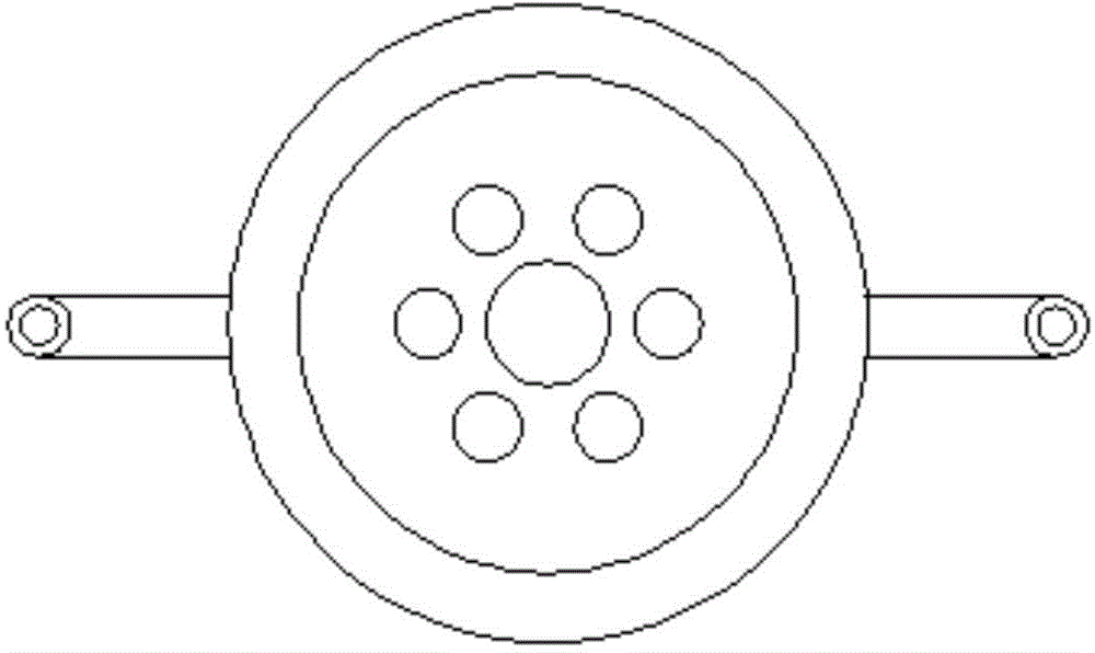
[0038] An air-heated fuel economizer, comprising: a casing 1, which is a hollow tube with two ends open, and a partition 4 is fixedly arranged in the inner cavity of the casing 1, and the partition 4 divides the inner cavity of the casing along the axis It is divided into an air inlet chamber 8 and an air outlet chamber 13 in the direction. The housing 1 is provided with a water chamber 2 in the wall around the air outlet chamber 13, and the separator 4 is provided with 6 uniformly distributed circular air holes 10 on the same circumference. , and the partition plate 2 is provided with a mounting seat 7 at the center of one side of the air intake chamber 8, the vacuum chamber 5 is fixedly connected with the mounting seat 7 by threads, and the center of the mounting seat 7 and the partition plate 4 is provided with a through hole to sleeve The ejector rod 11, the ejector rod 11 can slide along the through hole, one end of the ejector rod 11 extends into the inner cavity of the v...


PUM


Abstract

An air heating type fuel economizer comprises a casing, a partition plate, a water inlet pipe, a water outlet pipe, a valve, a vacuum chamber, a mandril and a sealing piece. The casing is a hollow pipe with openings at two ends, and a water cavity is arranged in the lateral wall of the casing. The partition plate is arranged in the cavity of the casing and divides the cavity of the casing into an air inlet cavity and an air outlet cavity along the axial direction. Air holes are formed in the partition plate so as to enable the air inlet cavity to be communicated with the air outlet cavity. The water inlet pipe is fixedly arranged on the casing outer wall, and an inner cavity of the water inlet pipe is communicated with the water cavity. The water outlet pipe is fixedly arranged on the casing outer wall, and an inner cavity of the water outlet pipe is communicated with the water cavity. The valve is arranged at the air outlet cavity port position so as to control opening or closing of an air outlet cavity port. The vacuum chamber is arranged on the partition plate. One end of the mandril is fixedly connected with the valve, and the other end of the mandril extends into the vacuum chamber. The sealing piece is arranged at one end of the mandril extending into the vacuum chamber. By heating the air, fuel atomization is thorough, engine power is increased, oil consumption is reduced, energy is saved, and the environment is protected.

Description

technical field [0001] The invention relates to the field of fuel economizers, in particular to an air heating type fuel economizer. Background technique [0002] Along with the continuous rise of energy prices, automobile fuel saving has become one of the topics that people are most concerned about. During the driving process of the car, since the engine needs to operate under various complicated working conditions, it is difficult for the engine intake system to ensure sufficient mixing of air and gasoline, which may easily cause gasoline to be incompletely combusted, increase fuel consumption, increase exhaust gas, and reduce power. In the current market, there are also fuel economizers to control the air volume required by the engine under different working conditions or to provide an oxygen-enriched environment for the combustion chamber, but most of the fuel economizers have complicated structures and are not convenient to attach to the car. [0003] In view of the ab...

Claims


Application Information

Patent Timeline
Patent Type & Authority Applications(China)
IPC IPC(8): F02M31/04
Inventor 李砚明
Owner 南宁明航节能科技有限公司
Learn More