
High-efficiency tree peeling machine

A technology of peeling machines and trees, applied in the direction of bark, wood processing equipment, manufacturing tools, etc., can solve the problem that the equipment is difficult to achieve automatic feeding, automatically adjust the cutting depth of the feeding space, the equipment is limited in use, and consumes a lot of manpower and material resources. and other problems to achieve the effect of improving processing quality, realizing adjustability and improving processing efficiency

Inactive Publication Date: 2014-02-26
SUZHOU WUZHONG DISTRICT GUANGFU XIANGXUE NURSERY GARDEN
View PDF0 Cites 12 Cited by
  • Summary
  • Abstract
  • Description
  • Claims
  • Application Information

AI Technical Summary

Problems solved by technology

[0002] The existing tree peeling methods generally include electric planing and machining. The electric planing requires a lot of manpower and material resources, and requires frequent maintenance, resulting in high processing costs. However, it is difficult for general machining equipment to realize automatic feeding and automatic adjustment of feeding. The space and the function of controlling the cutting depth, therefore, the equipment has high requirements on raw materials, the use of equipment is very limited, and the general processing equipment can only process one piece of wood at a time, and the processing efficiency is low

Method used


Image

  • High-efficiency tree peeling machine
  • High-efficiency tree peeling machine
  • High-efficiency tree peeling machine

Examples


Embodiment Construction

[0023] The present invention is described below in conjunction with accompanying drawing.

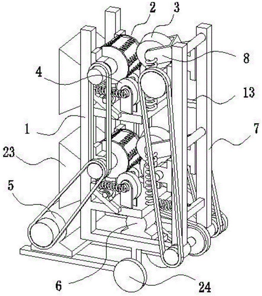
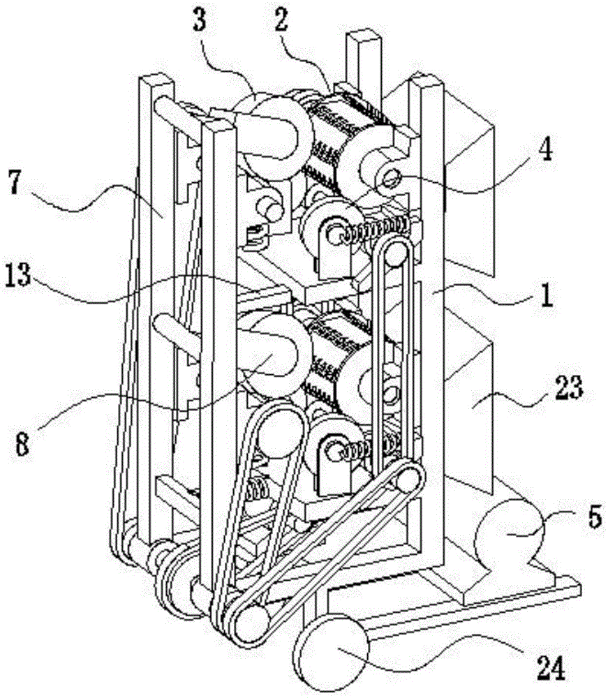
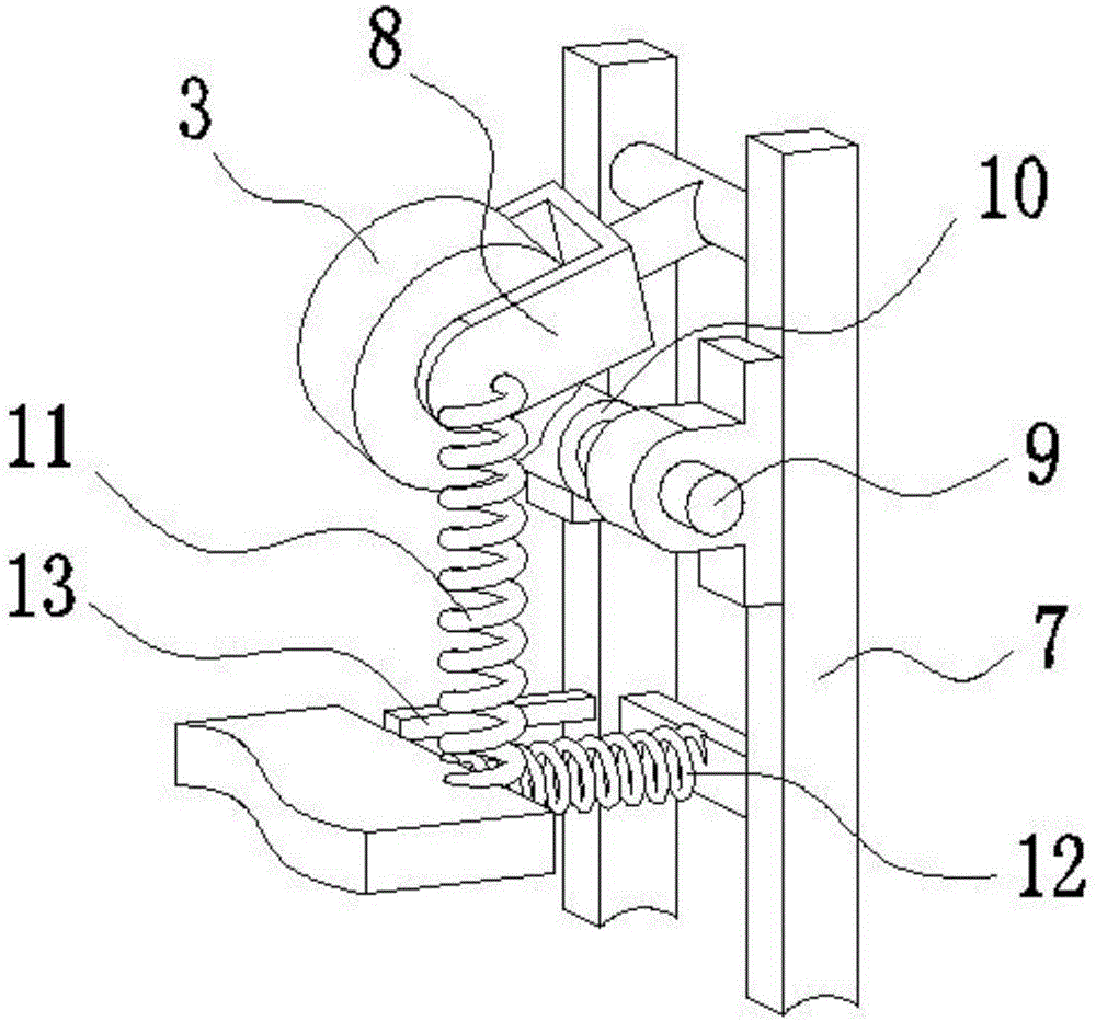
[0024] Such as Figure 1-5 As shown, a kind of high-efficiency tree peeling machine of the present invention comprises frame 1, driving device and two groups of cutting and feeding assemblies that are arranged up and down; The rear portion of described frame 1 is provided with rotatable rear frame 7; Each group of described cutting feeding assembly comprises cutterhead assembly 2, upper feeding wheel 3, lower feeding wheel 4, upper feeding wheel connecting arm 8, upper wheel shaft 9, lower connecting arm 14 and lower wheel shaft 15; 2 includes a blade 18, a cutter shaft disk 19 and a limit disk 20; the cutter shaft disk 19 is rotatably arranged on the frame 1, and the axis of the cutter shaft disk 19 is parallel to the feeding direction; the blade 18 has a plurality of , a plurality of blades 18 are obliquely and evenly arranged on the outer circumference of the cutter shaft disc 19; t...


PUM


Abstract

The invention discloses a high-efficiency tree peeling machine. The high-efficiency tree peeling machine comprises a rack, a driving device and a plurality of cutting and feeding subassemblies, wherein each cutting and feeding subassembly comprises a cutter head subassembly, an upper feeding wheel and a lower feeding wheel; the cutter head subassemblies are rotatably arranged on the rack; the axis of each cutter head subassembly is parallel to the feeding direction; a connecting line between each cutter head subassembly and the center of the corresponding upper feeding wheel and a connecting line between each cutter head subassembly and the center of the corresponding lower feeding wheel form an acute triangle; feeding space is reserved between each cutter head subassembly and the corresponding upper feeding wheel; feeding space is also reserved between each cutter head subassembly and the corresponding lower feeding wheel; the axes of the upper feeding wheels and the axes of the lower feeding wheels are not parallel to the axes of the cutter head subassemblies; the direction of the horizontal component, which acts on materials, of each upper feeding wheel and the direction of the horizontal component, which acts on the material, of each lower feeding wheel are consistent with the feeding direction; and the cutter head subassemblies, the upper feeding wheels and the lower feeding wheels are driven to rotate by the driving device. By the cutting and feeding subassemblies, a plurality of trees can be simultaneously processed by the high-efficiency tree peeling machine, and the processing efficiency is improved.

Description

technical field [0001] The invention relates to a tree peeling machine, in particular to a high-efficiency tree peeling machine with convenient operation, good processing effect and high production efficiency. Background technique [0002] The existing tree peeling methods generally include electric planing and machining. The electric planing requires a lot of manpower and material resources, and requires frequent maintenance, resulting in high processing costs. However, it is difficult for general machining equipment to realize automatic feeding and automatic adjustment of feeding. Space and the function of controlling the depth of cutting, therefore, the equipment has high requirements on raw materials, the use of equipment is very limited, and general processing equipment can only process one piece of wood at a time, and the processing efficiency is low. Contents of the invention [0003] In view of the above-mentioned technical problems, the purpose of the present inve...

Claims


Application Information

Patent Timeline
IPC IPC(8): B27L1/10
Inventor 府勤珠
Owner SUZHOU WUZHONG DISTRICT GUANGFU XIANGXUE NURSERY GARDEN
Learn More