
Practical positioner

A positioner and practical technology, applied in auxiliary devices, auxiliary welding equipment, welding/cutting auxiliary equipment, etc., can solve the problems of bumping, unstable load-bearing, and easy tipping of the rotary platform, and reduce welding deformation. , The effect of easy picking and placing of workpieces and quick operation

Inactive Publication Date: 2014-02-26
SHANDONG LISHIDE MACHINERY
View PDF14 Cites 6 Cited by
  • Summary
  • Abstract
  • Description
  • Claims
  • Application Information

AI Technical Summary

Problems solved by technology

At present, there are two main methods for welding the rotary platform, one is the L-shaped positioner, but due to the shape and weight of the rotary platform, the load bearing is unstable during the turning process, the rotary platform is easy to tip over, and the rotary platform is very prone to accidents The phenomenon of overturning creates potential safety hazards; the second method adopts the overturning operation method of driving, and the technical level is backward, which poses potential safety hazards for personnel and driving
There is an impact in this flipping method, which is likely to cause bumps, scratches and deformation of the rotary platform, leaving quality problems for subsequent processes
With the increase of production year by year, the use of the crane to turn and shift takes a long time to travel, which causes the crane to fail to meet the normal hoisting workload, which restricts the improvement of the overall production capacity, and the workpiece cannot be positioned and clamped, so it can only be welded manually instead of robots. , unable to reduce the labor intensity of workers

Method used


Image

  • Practical positioner
  • Practical positioner
  • Practical positioner

Examples


Embodiment Construction

[0018] The detailed description and technical content of the present invention are described below with the accompanying drawings, but the accompanying drawings are only provided for reference and description, and are not intended to limit the present invention.

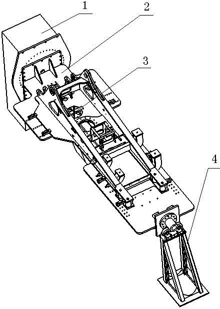
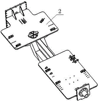
[0019] like Figure 1-3 As shown, the positioner of the present invention includes an overturning main base 1, a driven machine base 4, an overturning frame 2, a clamping and positioning device 3, an electrical system and a rotary system, etc. Specifically, the rotary system is respectively connected with the overturning main base 1 and the overturning One end of the frame 2 is connected, and the other end of the flip frame 2 is connected with the driven base 4. The slewing system includes a reducer 6, a slewing ring ring 8, and a slewing ring 9. One end of the reducer 6 is connected to the motor 5, and the other end is connected to the slewing ring 9. The slewing includes the slewing ring 8 and the slewing support ...


PUM


Abstract

The invention discloses a practical positioner comprising a rotary system, a overturning frame and a driven seat. One end of the overturning frame is connected to the rotary system, and the other end is connected to the driven seat. The rotary system is fixed on an main overturning seat. The rotary system comprises a motor, a reducer and a rotary support. One end of the reducer is connected to the motor, and the other end is connected to the rotary support connected to the overturning frame. The rotary support comprises a rotary support inner gear ring and a rotary support outer gear ring. The rotary support outer gear ring is connected to the overturning frame, and the rotary support inner gear ring is connected to the main overturning seat through a connecting disc and is engaged with the rotary support outer gear ring. A positioning clamping device is mounted on the overturning frame. The practical positioner is simple in structure and safe to operate, can meet positioning requirements of varieties of excavator rotary platforms, has better generality, can overturn more stably, can overturn and position a workpiece in 360 degrees, is operated with a limit clamping device, meets positioning and clamping requirements of the excavator rotary platforms, and meets the welding requirements of the rotary platforms.

Description

technical field [0001] The invention relates to a displacement device for large components, in particular to a practical displacement machine. Background technique [0002] Positioner refers to a special machine that can change the original position of the workpiece, that is, flip the workpiece to the required position, so that the operator can weld, assemble or operate. A positioner is sometimes called a flipper. At present, there are two main methods for welding the rotary platform, one is the L-shaped positioner, but due to the shape and weight of the rotary platform, the load bearing is unstable during the turning process, the rotary platform is easy to tip over, and the rotary platform is very prone to accidents The phenomenon of overturning creates potential safety hazards; the second method adopts the overturning operation mode of driving, and the technical level is backward, and there are potential safety hazards for personnel and driving. There is impact in this f...

Claims


Application Information

Patent Timeline
IPC IPC(8): B23K37/047B25B11/00
CPCB23K37/047
Inventor 王经聪臧华宋祥献崔明赵贵革英玉振丁万涛田中航冯海凤薛彦华
Owner SHANDONG LISHIDE MACHINERY
Learn More