
360 degree pneumatic cleaning purger

A purging device and cleaning brush technology, applied in the direction of cleaning methods, cleaning methods and appliances, chemical instruments and methods using gas flow, etc., can solve the problems of insulators not being able to clean 360 degrees, high-voltage insulation safety hazards, and stable operation of the power grid. and other problems to achieve the effect of eliminating hidden dangers of insulation, light weight and small inertia

Active Publication Date: 2016-08-31
STATE GRID CORP OF CHINA +2
View PDF8 Cites 1 Cited by
  • Summary
  • Abstract
  • Description
  • Claims
  • Application Information

AI Technical Summary

Problems solved by technology

Manual cleaning must be carried out with power outages. Even if there are alternate power outages, it will cause certain risks and hidden dangers to the stable operation of the power grid.
The insulator cleaning machines that have come out are all driven by power cords, electric drills or motors, and there are potential safety hazards in high-voltage insulation. They can only clean 1 / 3 or 1 / 4 of the outer circumference of the insulator at a time, and cannot clean the insulator 360 degrees; the cleaning The machine needs to change 3-4 working positions around the insulator on the ground, move the insulation lifting bracket and cleaning equipment 3-4 times, and perform 3-4 cleanings in different directions of the insulator to complete the 360-degree cleaning of an insulator

Method used


Image

  • 360 degree pneumatic cleaning purger
  • 360 degree pneumatic cleaning purger
  • 360 degree pneumatic cleaning purger

Examples


specific Embodiment

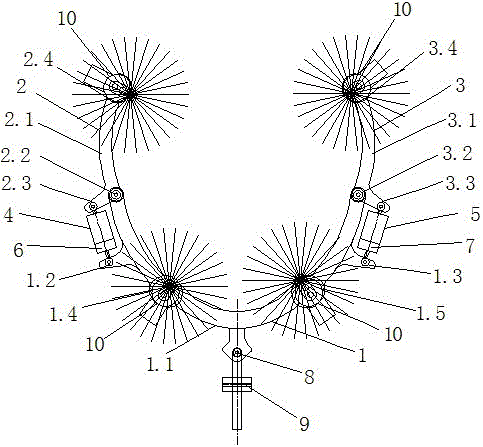
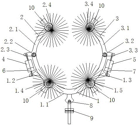
[0029] Such as figure 1 , figure 2 As shown, the 360-degree pneumatic cleaning purger includes: a fixed frame 1, a left movable mechanical arm 2 and a right movable mechanical arm 3, a left cylinder 4 and a right cylinder 5, a left pneumatic solenoid valve 6 and a right pneumatic solenoid valve 7, Horizontal angler 8, vertical angler 9 and four pneumatic sweeping brushes 10.

[0030] The fixed frame 1 includes a fixed frame 1.1, a cylinder connecting frame 1.2, a cylinder connecting frame 1.3, a cleaning brush fixing seat 1.4, and a cleaning brush fixing seat 1.5. The fixed frame 1.1 is an insulating hollow material, and compressed air circulates in the empty hollow cavity.

[0031] The left and right movable mechanical arms are articulated movable mechanical arms, and the left movable mechanical arm 2 and the right movable mechanical arm 3 respectively comprise a left movable arm bar 2.1 and a right movable arm bar 3.1, a left rotating connecting shaft 2.2, a right rotati...


PUM


Abstract

The invention discloses a 360-degree pneumatic sweeping and blowing device for sweeping a post insulator. The 360-degree pneumatic sweeping and blowing device comprises a fixed machine frame, a left movable mechanical arm, a right movable mechanical arm, a left cylinder, a right cylinder, a left pneumatic electromagnetic valve, a right pneumatic electromagnetic valve, a horizontal angle turning device, a vertical angle turning device and four pneumatic blowing and sweeping brushes. Hinges at two ends of the fixed machine frame are connected with the left movable mechanical arm and the right movable mechanical arm, the left cylinder and the right cylinder are arranged on the outer sides of two ends of the fixed machine frame, the left pneumatic electromagnetic valve and the right pneumatic electromagnetic valve are arranged on the left cylinder and the right cylinder or fixed mechanical arms respectively, the outer side of a symmetrical axis of the fixed machine frame is connected with the horizontal angle turning device, the horizontal angle turning device is connected with the vertical angle turning device, and the four pneumatic blowing and sweeping brushes are installed on the fixed machine frame and the movable mechanical arms respectively. The whole 360-degree pneumatic sweeping and blowing device is installed on an insulating rod or an insulating lifting mechanism through the vertical angle turning device. The sweeping and blowing device can perform random and repeated 360-degree sweeping and blowing on the insulator and is free of sweeping blind corners and suitable for high and low voltage live working of various voltage grades and non-electrified working.

Description

technical field [0001] The invention relates to a pneumatic cleaning machine for cleaning post insulators, in particular to a pneumatic cleaning purger for 360-degree rotating brush cleaning and synchronous cleaning of insulators. Background technique [0002] Substation insulators are the support and insulation facilities for high-voltage equipment in substations. Due to being outdoors all the year round, the surface of insulators is prone to form a dirty layer. These filthy thing Wet by heavy fog, light rain, etc., will form electrolytes to destroy insulation, and easily cause pollution flashover accidents. Pollution flashover accidents can cause line tripping and power outages in the slightest, and disconnection of the power grid in severe cases, resulting in large-scale catastrophic power outages. Therefore, regular cleaning and decontamination of insulators is required. [0003] Our country has carried out anti-pollution flashover work for more than 40 years. The wi...

Claims


Application Information

Patent Timeline
Patent Type & Authority Patents(China)
IPC IPC(8): B08B7/04B08B5/02B08B1/04B08B13/00
CPCB08B1/002B08B1/04B08B5/02B08B7/04
Inventor 智全中张亮赵维亮张献伟吴越人
Owner STATE GRID CORP OF CHINA
Learn More