
Near-field antenna

A near-field antenna and near-field coupling technology, which is applied in the field of radio frequency identification, can solve the problem of large thickness of the reader antenna, and achieve the effects of reducing the thickness, strengthening the magnetic field strength, and reducing the distance

Active Publication Date: 2014-02-19
ZHONGTIAN BROADBAND TECH +1
View PDF2 Cites 24 Cited by
  • Summary
  • Abstract
  • Description
  • Claims
  • Application Information

AI Technical Summary

Problems solved by technology

Moreover, the thickness of the reader antenna in this way is relatively large

Method used


Image

  • Near-field antenna
  • Near-field antenna
  • Near-field antenna

Examples


Embodiment Construction

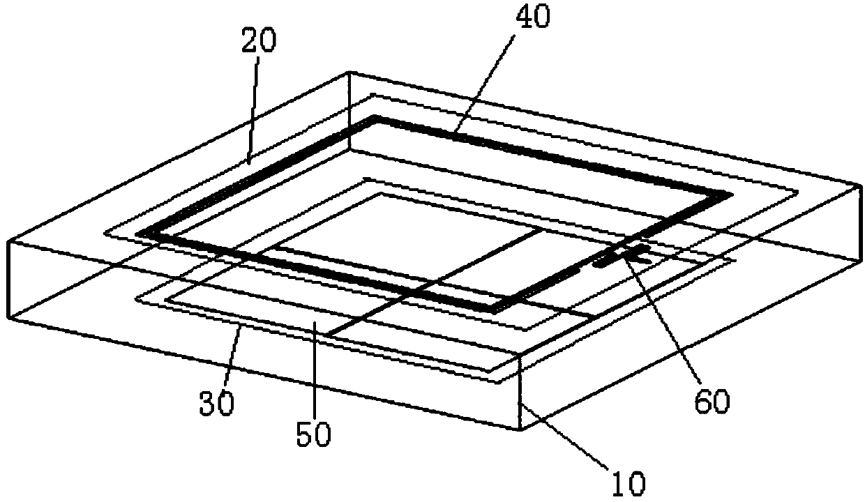
[0024] figure 1 A schematic structural diagram of a near-field antenna in an embodiment of the present invention is shown, and the near-field antenna is an electrically large-sized near-field antenna used for a radio frequency identification reader. It includes a metal box 10 , a first dielectric substrate 20 , a second dielectric substrate 30 , a near-field coupling coil 40 , a metal patch array 50 , and an input terminal 60 .

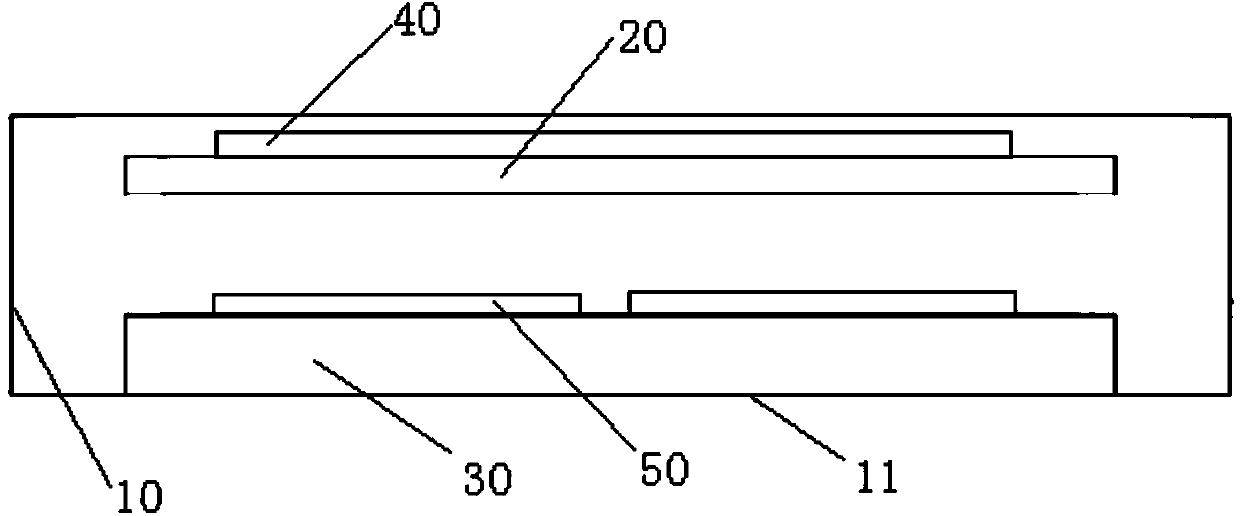
[0025] Also refer to figure 2 , The metal box body 10 is used to shield external electromagnetic interference. The second dielectric substrate 30 is disposed in the metal box 10 and on the bottom plate 11 for mounting the metal patch array 50 thereon and isolating the metal patch array 50 from the bottom plate 11 of the metal box 10 . The first dielectric substrate 20 is disposed in the metal box 10 and adjacent to the opening of the metal box 10 for mounting the near-field coupling coil 40 on a surface facing the opening. The near-field coupling ...


PUM


Abstract

The invention relates to a near-field antenna. The near-field antenna comprises a metal box body, a first dielectric substrate, a near-field coupling coil, an input end and a second dielectric substrate. The metal box body is used for shielding outside electromagnetic interference and comprises a tabulate base board and a cover body fixed to the base board, and an opening exactly facing the base board is formed in the cover body. The first dielectric substrate, the near-field coupling coil and the input end used for inputting radio-frequency signals into the near-field coupling coil are contained in the metal box body, and the first dielectric substrate is placed to be adjacent to the opening. The second dielectric substrate is fixedly arranged in the metal box body and on the base board, the second dielectric substrate, the first dielectric substrate and the base board are parallel to each other, and a metal paster array is arranged on the upper surface of the second dielectric substrate. The near-field antenna has the advantages of enhancing the magnetic field strength within a near-field range and reducing the thickness of the near-field antenna.

Description

technical field [0001] The invention relates to the technical field of radio frequency identification, in particular to a near-field antenna. Background technique [0002] The reader of the RFID system transmits the modulated radio frequency signal to the tag. Tags consist of an antenna and chip. The chip receives power from the antenna to modulate the transmitted signal by changing its input impedance. Such a system would allow us to read or write multiple tags simultaneously, conveniently and selectively activate remote sensors based on their unique IDs. [0003] At present, UHF near-field radio frequency identification technology has received great attention. A major challenge in the application of UHF near-field RFID is to design an electrically large-sized reader antenna, which requires the antenna to have a uniform and sufficiently strong magnetic field distribution in the identifiable area. The traditional solid coil whose circumference is almost as long as the wa...

Claims


Application Information

Patent Timeline
IPC IPC(8): H01Q1/22H01Q1/38
Inventor 施金李宇翔陈建新褚慧唐慧周立衡包志华
Owner ZHONGTIAN BROADBAND TECH
Learn More