
Plasma processing equipment

A plasma and processing equipment technology, applied in the field of plasma processing equipment, can solve the problems that affect the efficiency of plasma processing equipment, the mechanical parts are easily damaged, and the structure is complicated, and achieve the effects of good fixation, reduced maintenance costs, and simple operation

Active Publication Date: 2014-02-19
BEIJING NAURA MICROELECTRONICS EQUIP CO LTD
View PDF7 Cites 6 Cited by
  • Summary
  • Abstract
  • Description
  • Claims
  • Application Information

AI Technical Summary

Problems solved by technology

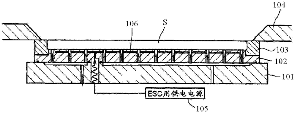
[0005] This way of using electrostatic force to fix the wafer S is fixed on the surface of the tray 102, but the tray 102 still needs a mechanical pressure ring 104 to fix it. It not only has a complex structure, high cost, and troublesome operation, but also the mechanical parts are easily damaged, and the maintenance work will affect the plasma. Efficiency in the use of body processing equipment

Method used


Image

  • Plasma processing equipment
  • Plasma processing equipment
  • Plasma processing equipment

Examples


Embodiment Construction

[0053] In order to enable those skilled in the art to better understand the technical solution of the present invention, the plasma processing device provided by the present invention will be described in detail below with reference to the accompanying drawings.

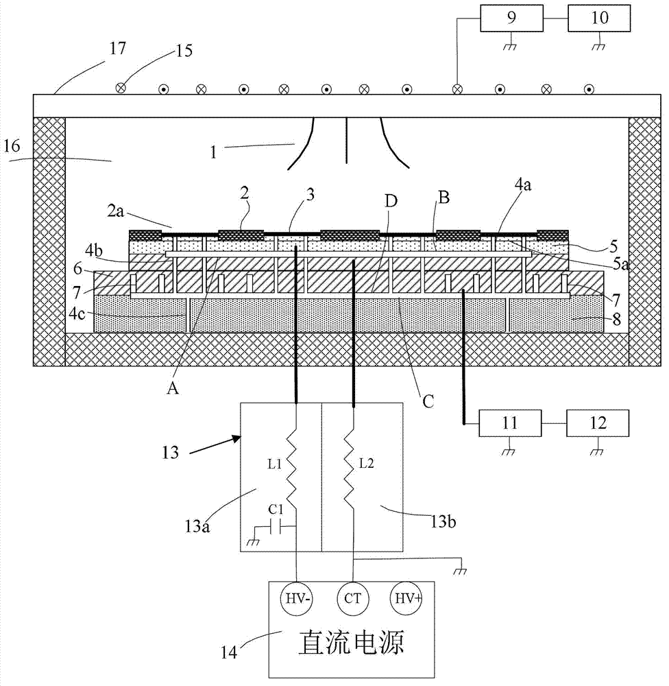
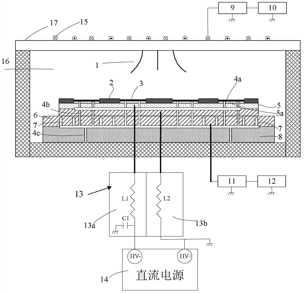
[0054] An embodiment of the present invention provides a plasma processing device, figure 2 It is a schematic cross-sectional view of a partial structure of a plasma processing device according to an embodiment of the present invention. Such as figure 2 As shown, the plasma processing apparatus includes a reaction chamber 16, the walls of which are grounded. The bottom of the reaction chamber 16 is provided with a chuck base 8, the chuck 6 is fixed on the top of the chuck base 8, and the tray 5 is placed on the bearing surface of the chuck 6 (the upper surface of the chuck shown in the figure). 5 is used to carry the wafer 3. A dielectric window 17 is provided on the top of the reaction chamber 16 , and the indu...


PUM


Abstract

A plasma processing apparatus comprises a reaction chamber (20), an excitation radio-frequency power source (13), a direct-current power source (24), an upper electrode, and a chip support device disposed in the reaction chamber and at a position relative to the upper electrode, the upper electrode being connected to the excitation radio-frequency power source to generate plasma (10) in the reaction chamber. The chip support device comprises a tray (21) for carrying a chip and a chuck (23), a tray electrode is provided in the tray, the tray is placed on the chuck and is electrically insulated from the chuck, the tray and the chuck are both electrically insulated from the plasma, the tray electrode is electrically connected to a positive output terminal or a negative output terminal of the direct-current power source, a chuck electrode is provided in the chuck, and the chuck electrode is grounded, so that a voltage difference exists between the tray and the chuck and exists between the tray and the chip. The plasma processing apparatus is advantageous in being easy to operate, having high reliability, a simple structure and a low cost, and being not easily damaged.

Description

technical field [0001] The invention belongs to the field of semiconductor processing and relates to plasma processing equipment. Background technique [0002] ICP plasma dry etching equipment is a common equipment for processing semiconductor devices. In order to process multiple wafers at the same time, multiple wafers are often placed on the surface of a tray with a large size, and then the tray is placed on the carrying surface of the chuck of the plasma processing chamber for processing. [0003] In the actual process, the plasma will cause the temperature of the wafer to exceed the temperature required by the process, so the temperature of the wafer needs to be controlled. The traditional temperature control method is to blow refrigerant gas (such as helium) on the back of the wafer (the other side opposite to the processing surface of the wafer), and adjust the temperature of the wafer with the help of refrigerant gas. In order to fix the wafer and avoid leakage of ...

Claims


Application Information

Patent Timeline
Patent Type & Authority Applications(China)
IPC IPC(8): H01J37/32H01L21/683
CPCH01L21/6833H01J37/32091H01J37/32715
Inventor 李玉站
Owner BEIJING NAURA MICROELECTRONICS EQUIP CO LTD
Learn More