
Power cable insulation monitoring system

A technology for insulation monitoring and power cables, applied in the direction of measuring electricity, measuring devices, measuring electrical variables, etc., can solve problems such as the inability to realize random cable detection, hidden dangers to the personal safety of operators, and influence on production and life, and achieve the goal of overcoming close-range operation detection equipment, ensuring accuracy and reliability, and improving the effect of power supply service quality

Inactive Publication Date: 2014-02-19
STATE GRID CORP OF CHINA +1
View PDF6 Cites 6 Cited by
  • Summary
  • Abstract
  • Description
  • Claims
  • Application Information

AI Technical Summary

Problems solved by technology

[0002] In actual use, there are strict assessment standards for the insulation performance of transmission cables in some high-voltage circuits or high-power low-voltage circuits. Low-voltage shaking meters, multimeters and other equipment, on the one hand, the detection accuracy of these devices is low, and the detection work is cumbersome. The detection must be carried out when the circuit is completely powered off, and it is impossible to realize the random detection of the cable in the working state. Therefore, the traditional On the one hand, the testing equipment can easily cause cable insulation leakage or mistesting, and on the other hand, it also causes the interruption of power transmission or power supply, which seriously affects the normal production and life.
At the same time, in the inspection and maintenance, especially when measuring the insulation level of the power supply line, it is necessary to apply extremely high voltage to the cable, which greatly exceeds the range of human body safety voltage, and traditional equipment operators must directly operate the testing equipment. The risk of electric shock is extremely high, which brings great hidden dangers to the personal safety of operators

Method used


Image

  • Power cable insulation monitoring system
  • Power cable insulation monitoring system

Examples


Embodiment Construction

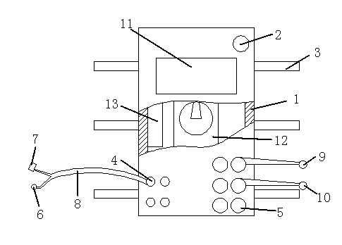
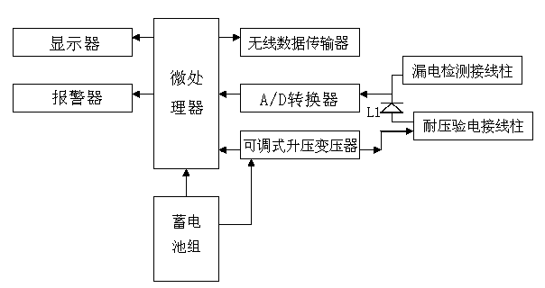
[0015] Such as figure 1 and 2 As shown, a power cable insulation monitoring system, the power cable insulation monitoring system is composed of a housing 1, a leakage electric contact, a withstand voltage electric contact, a controller and an alarm 2, and the outer surface of the housing 1 is An elastic connection belt 3 is provided, and at least two leakage detection terminal posts 4 and at least two withstand voltage test terminal posts 5 are provided on the upper surface of the housing 1, and at least one alarm device 2 is provided in addition, and the leakage test contact is provided by An electrostatic sensor 6 and a Hall closed-loop leakage current sensor 7 are connected in parallel, and are connected to the leakage detection terminal 4 through a wire 8. The pressure-resistant electric contact is composed of an internal contact 9 and an external contact 10. The internal contact 9 and the external contact 10 are both cylindrical, and are respectively connected to the wit...


PUM


Abstract

The invention discloses a power cable insulation monitoring system which is composed of a shell, an electric leakage electric-verification contact, a voltage-tolerance electric-verification contact, a controller and an alarm. An elastic connecting strip is arranged at the outer surface of the shell, at least two electric leakage detection binding posts and at least two voltage-tolerance electric-verification binding posts are arranged on the upper surface of the shell, at least one alarm is also arranged, a displayer, an adjustable boosting transformer, a storage battery set, an A / D converter, a microprocessor, and a wireless data transmitter form the controller and are all arranged in the shell, wherein an adjusting block of the adjustable boosting transformer is embedded in the upper surface of the shell. The power cable insulation monitoring system is simple in structure and convenient to operate, can randomly detect the insulation grade change situation when the cable is in working state during the whole process, gives an alarm in time, and overcomes the defects that operation staff must be closed to the detection equipment to operate the detection equipment, and therefore the potential safety hazard of electric shock during the detection process is eradicated.

Description

technical field [0001] The invention relates to a power cable insulation monitoring system, which belongs to the field of power detection equipment. Background technique [0002] In actual use, there are strict assessment standards for the insulation performance of transmission cables in some high-voltage circuits or high-power low-voltage circuits. Low-voltage shaking meters, multimeters and other equipment, on the one hand, the detection accuracy of these devices is low, and the detection work is cumbersome. The detection must be carried out when the circuit is completely powered off, and it is impossible to realize the random detection of the cable in the working state. Therefore, the traditional On the one hand, the testing equipment can easily cause cable insulation leakage or mistesting, and on the other hand, it also causes the interruption of power transmission or power supply, seriously affecting normal production and life. At the same time, in the inspection and m...

Claims


Application Information

Patent Timeline
Patent Type & Authority Applications(China)
IPC IPC(8): G01R31/12G01R31/02
Inventor 薛双勋
Owner STATE GRID CORP OF CHINA
Learn More