Regulating valve

A regulating valve and valve needle technology, applied in the field of regulating valves, can solve problems such as large cutting parameters, difficult machining procedures, small machining tools, etc., to meet the needs of small flow adjustment, reduce production costs, and improve manufacturing accuracy.

Inactive Publication Date: 2014-02-19
BEIJING XIONGCHUAN VALVE MFG
View PDF6 Cites 4 Cited by
  • Summary
  • Abstract
  • Description
  • Claims
  • Application Information

AI Technical Summary

Problems solved by technology

[0005] Regardless of the small-diameter adjustment hole on the valve seat or the slender conical section of the valve needle, they are all difficult machining processes that are avoided by precision lathe machining, and are mechanical design structures that lead to high production costs.
For the small hole of the valve seat with a diameter of less than 1 mm, the machining tool is smaller and the mechanical rigidity is also low. During high-speed machining, the material has a great resistance to the tool. In addition, the cantilever of the tool is long, which makes the tool easy to vibrate during processing. , the production efficiency is greatly reduced
These factors make it difficult to guarantee the dimensional tolerance and shape tolerance of the hole, and the production cost is high
Besides, for the slender section of the cone valve needle, although the rigidity of the machining tool can be guaranteed, the workpiece itself has a long cantilever and low rigidity and is easy to bend. It is required that large cutting parameters cannot be used when machining the cone valve needle, resulting in a decrease in production efficiency. Increased production costs
At the same time, the existence of processing resistance also makes it difficult to guarantee the size and shape tolerance of parts

Method used


Image

  • Regulating valve
  • Regulating valve
  • Regulating valve

Examples


Embodiment Construction

[0054] In order to make the object, technical solution and advantages of the present invention clearer, the implementation manner of the present invention will be further described in detail below in conjunction with the accompanying drawings.

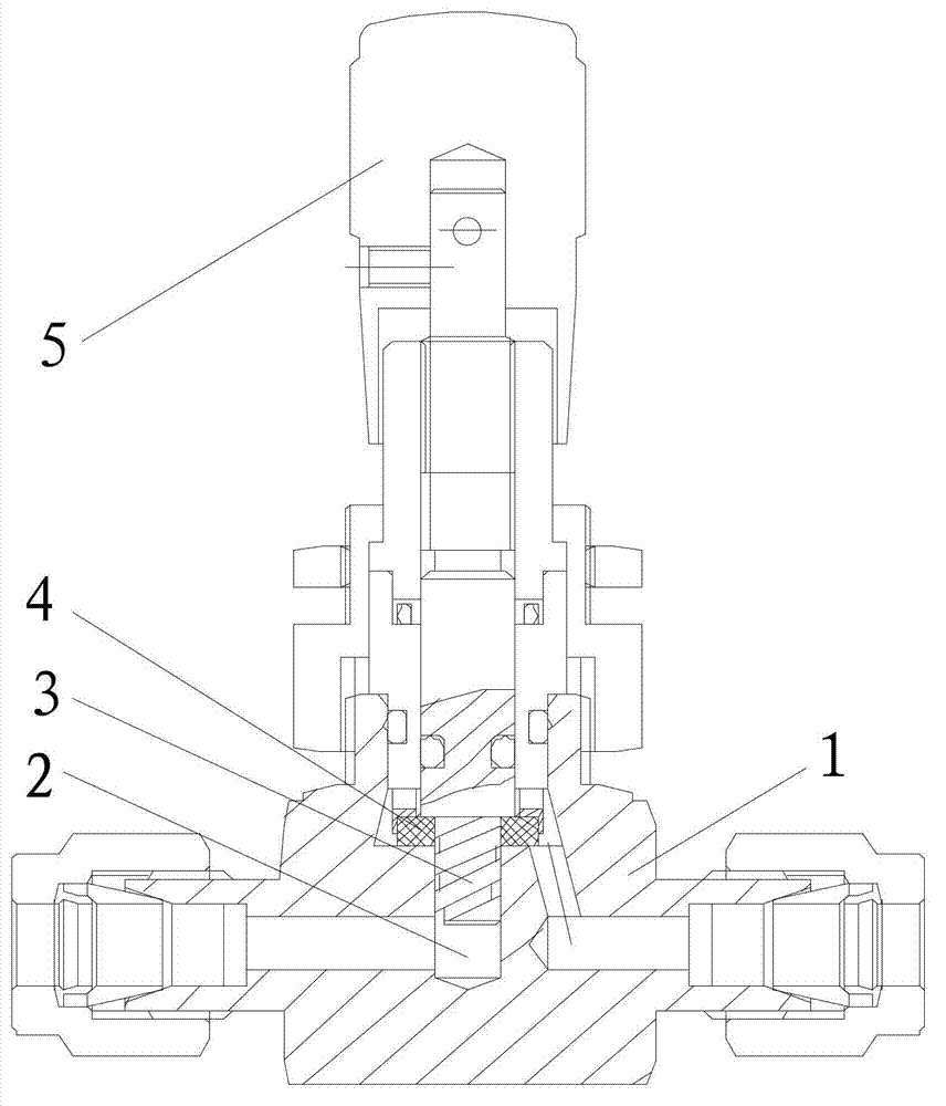
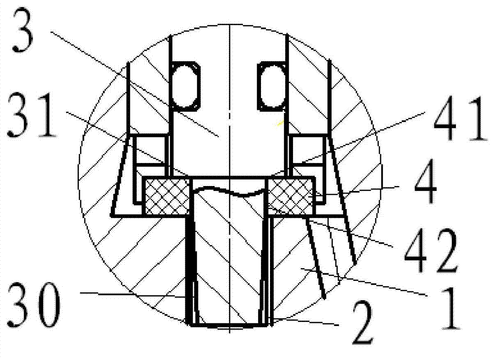
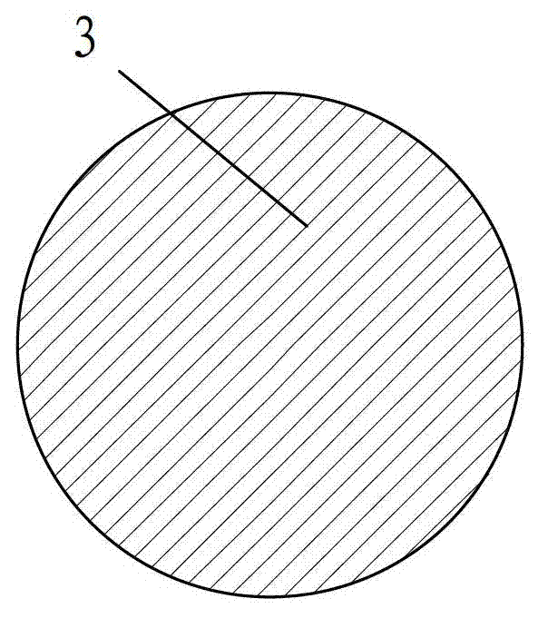
[0055] see figure 1 and figure 2 , a regulating valve, comprising a valve seat 4, a valve seat hole 42 is arranged in the valve seat 4, a valve needle 3 is arranged in the valve seat hole 42, a groove 30 is arranged on the side wall of the valve needle 3, and the groove 30 can Change the size of the flow surface.

[0056] By processing the groove on the side wall of the valve needle, the adjustment of the small flow can be realized, and the invention is easy to process and has low production cost.

[0057] In the present invention, a detailed description is given by taking the cylindrical valve seat hole with the cylindrical valve needle and two axial linear grooves on the side wall as an example:

[0058] On the basis of the above...


PUM


Abstract

The invention discloses a regulating valve comprising a valve seat, a valve body and a handle. A valve seat hole is formed in the valve seat. A valve needle is arranged in the valve seat hole. Grooves are formed in the side walls of the valve needle. Size of flowing face can be changed by the grooves. The valve seat is mounted on the valve body. A flowing hole is formed in the valve body. The bottom of the valve needle extends into the flowing hole. The handle is connected with the valve needle. When the valve needle is in the shape of a cone, the cross section areas of grooves in the cone are the same; when the valve needle is in the shape of a cylinder, the cross section areas of grooves in the cylinder decrease gradually from bottom to top. No costly equipment and process is needed for processing of the valve seat hole and the valve needle of the regulating valve, only processing of the grooves in the side walls of the valve needle is needed, and accordingly, production cost is low. Through the grooves, micro-flow regulation can be realized, limitation of the micro-flow regulation on valve seat pores and elongated valve-needle conical sections is broken through, production cost is reduced, production accuracy is improved, and requirements on precise micro-flow regulation are met.

Description

technical field [0001] The invention relates to the field of valves, in particular to a regulating valve. Background technique [0002] Regulating valves are well known in the field of instrumentation valves. A common regulating valve realizes the regulation of the fluid medium flow by controlling the size of the annular flow surface formed between the small taper valve needle and the cylindrical valve seat hole. [0003] In the state of the art, micro-flow regulation is achieved by designing a smaller cylindrical valve seat hole and a thinner conical valve needle. The already thin conical valve needle is designed to be longer due to the continuous multi-turn flow regulation requirement in operation. The ratio of the axial length of the conical section of the valve needle on the market to the diameter of the largest cone section of the valve needle is mostly more than 10 times. [0004] In the process of realizing the present invention, the inventor finds that there are at...

Claims


Application Information

Patent Timeline
IPC IPC(8): F16K17/20
CPCF16K1/36F16K1/385F16K1/52
Inventor 刘茯蔚赵曦赵强
Owner BEIJING XIONGCHUAN VALVE MFG
Why Eureka
Try Eureka