A radial position adjustment assembly for a roller shaft-like revolving body

A technology of gyratory bodies and roller shafts, which is applied to transmission parts, belts/chains/gears, mechanical equipment, etc. It can solve the problems of cylinder or hydraulic cylinder stuck, slow movement, many parts, etc., and achieves convenient maintenance and simple structure reliable effect

Active Publication Date: 2016-09-28
SHENZHEN RUNTIANZHI DIGITAL EQUIP
View PDF10 Cites 0 Cited by
  • Summary
  • Abstract
  • Description
  • Claims
  • Application Information

AI Technical Summary

Problems solved by technology

[0004] One is to drive the two ends of the rotary body to move synchronously through the motor, and convert the optional motion of the motor into linear motion. This method generally requires the use of more complicated structures such as screw screws, not only many parts, but also the equipment itself. Cost and later maintenance costs are high
[0005] The other is to use hydraulic or pneumatic cylinders to drive the two ends of the rotary body to move synchronously. This method has fewer parts, simple driving structure and easy maintenance. However, the accuracy of the cylinder or hydraulic cylinder itself is affected by the air source or hydraulic pressure. The source, the length of the pipeline, and the size of the load are greatly affected, so it is difficult to keep the synchronization of the cylinders or hydraulic cylinders at both ends consistent, which will cause one end of the roller shaft to move faster and the other end to move slowly. When the difference is large, it will cause damage to the connecting parts, and even cause the cylinder or hydraulic cylinder to be stuck.

Method used


Image

  • A radial position adjustment assembly for a roller shaft-like revolving body
  • A radial position adjustment assembly for a roller shaft-like revolving body

Examples


Embodiment Construction

[0024] The core of the present invention is to provide a radial position adjustment assembly of a roller-type rotating body, so that when adjusting the radial position, it can effectively ensure that the two ends of the roller-type rotating body move synchronously, thereby effectively protecting the rotating body. Various connection parts and drive units.

[0025] In order to enable those skilled in the art to better understand the solution of the present invention, the present invention will be further described in detail below in conjunction with the accompanying drawings and specific embodiments.

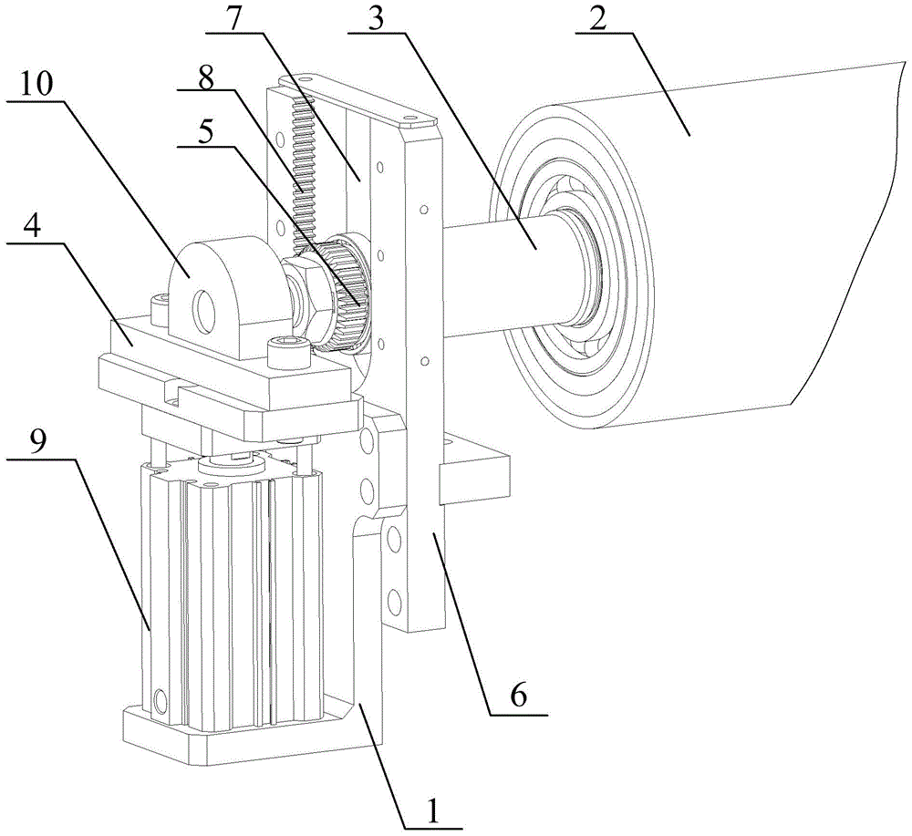
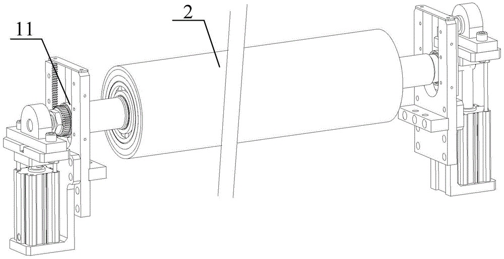
[0026] Please also refer to figure 1 and figure 2 ,in figure 1 It is a partial structural schematic diagram of the radial position adjustment assembly of the roller-type rotary body provided in the embodiment of the present invention, figure 2 It is a schematic diagram of the overall structure of the radial position adjustment assembly of the roller-type rotator provided in ...


PUM


Abstract

The invention relates to a radial position adjustment assembly for a roll shaft revolving body. The radial position adjustment assembly comprises bottom frames and a revolving main body, wherein installation shafts which are concentric with the revolving main body are fixedly connected to the two ends of the revolving main body, the installation shafts at the two ends of the revolving main body are arranged on two adjustment bases respectively in a rotatable mode, the adjustment bases are independent of each other and can move along the radial direction of the revolving main body, and at least one of the adjustment bases is connected with a driving end of a drive device. the radial position adjustment assembly further comprises cylindrical gears and guide plates, wherein the cylindrical gears are arranged on the installation shafts at the two ends of the revolving main body and of the same specification, the guide plates are fixedly connected to the bottom frames and located at the two ends of the revolving main body, a radial guide groove is formed in each guide plate, the cylindrical gears are embedded into the radial guide grooves, racks which are matched with each cylindrical gear are arranged on a lateral side of the corresponding guide groove, and the racks are meshed with the gears. The radial position adjustment assembly is simple and reliable in structure and convenient to maintain, the synchronism of movement of the two ends of the revolving main body can be effectively ensured, and therefore each connection part of the revolving main body and the drive device can be effectively protected.

Description

technical field [0001] The invention relates to the technical field of position adjustment of a large-scale roller-type rotary body, in particular to a radial position adjustment assembly of a roller-type rotary body. Background technique [0002] The two ends of the roller-type rotary body are generally installed on the support seat through bearings. In the actual production process, due to various needs, the position of the roller-type rotary body may be adjusted in the radial direction. For small-sized roller-type rotary bodies , its radial position adjustment is relatively easy to realize, and the radial position adjustment can be carried out by driving its two ends or the middle. The seat generally has a driving device that can drive the roller-type rotator to move radially. When adjusting the radial position, it is necessary to ensure that the two ends of the roller-type rotator move synchronously. [0003] At present, the driving devices used in the radial adjustment...

Claims


Application Information

Patent Timeline
Patent Type & Authority Patents(China)
IPC IPC(8): F16H57/022
CPCF16H57/022F16H2057/0222
Inventor 李亚西颜昌文江洪李力张昕
Owner SHENZHEN RUNTIANZHI DIGITAL EQUIP
Why Eureka
Try Eureka