Injection system with far-end feeding function

An injection system and remote technology, applied in the field of injection systems for remote feeding, can solve problems such as unsuitable syringes, reduce size and design requirements, easily and quickly repeat feeding multiple times, and reduce repeated withdrawal and feeding. The effect of the number of times in the human body

Pending Publication Date: 2020-03-31
NINGBO DIOCHANGE MEDICAL TECH CO LTD
View PDF0 Cites 0 Cited by
  • Summary
  • Abstract
  • Description
  • Claims
  • Application Information

AI Technical Summary

Problems solved by technology

[0008] In view of this, the purpose of this application is to provide a remote feeding injection system, which is used to solve the problem that traditional syringes cannot be applied to minimally invasive surgery and minimally invasive interventional surgery to inject drugs or fillers into deep lesions in the human body. The system is easy to add and inject relatively viscous injections. The utilization of the injections is high and the injection volume is controlled precisely, which is convenient for real-time injection at any position in the body. Requirements for multiple feeding and injections in vivo

Method used


Image

  • Injection system with far-end feeding function
  • Injection system with far-end feeding function
  • Injection system with far-end feeding function

Examples


Embodiment 1

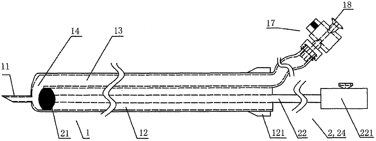
[0083] Such as Figure 1A As shown, the present application provides a remote-feeding injection system (hereinafter referred to as "the system"), which includes the injection assembly 1 including the feeding chamber 13 and the injection chamber 12, the pushing assembly 2 and the For the injection 3 in the feeding chamber 13, the remote end of the system is provided with an injection needle 11, the injection needle 11 is a hollow structure, and a backstop mechanism 17 and a communication port 14 are provided in the system, and the communication port 14 makes the feeding chamber 13 communicate with the inner cavity of the injection chamber 12 and the injection needle 11, when the injection 3 in the feeding chamber 13 is input into the injection chamber through the communication port 14 12, the pushing assembly 2 can move towards the proximal direction, so as to form a negative pressure state in the injection cavity 12 .

[0084] The pushing assembly 2 includes a power source 25 ...

Embodiment 2

[0107] Based on the first embodiment, the difference between the second embodiment and the first embodiment is that a second backstop mechanism 19 is further provided between the injection needle 11 and the communication port 14, so that the injection cavity 12 And the fluid in the injection needle 11 can only flow from the proximal end to the distal end, preventing external gas and human blood from flowing back into the injection cavity 12 from the injection needle 11, and finally endowing the system with any position in the body. Sufficient safety when feeding multiple times "in situ". The specific structure of the second backstop mechanism 19 can be designed similarly or identically to the various described backstop mechanism 17 described in Embodiment 1, and the structure that can be used for the second backstop mechanism 19 also includes a manual on-off valve The structure and the structure of the automatic on-off valve will be described below by enumerating the embodimen...

Embodiment 3

[0111] The difference between the present embodiment and the first embodiment is that the system is also provided with a monitoring mechanism 7, so as to enhance the effectiveness of the medical staff to use the system to judge the penetration depth of the injection needle at the position of the target lesion. The monitoring mechanism 7 can be implemented in various ways.

[0112] In one embodiment, as Figure 3A and Figure 3B As shown, the monitoring mechanism 7 is a tube body 71 in fluid communication with the injection cavity 12 and the injection needle 11, and a monitoring device that is slidingly sealed with the inner cavity of the tube body 71 is provided in the tube body 71. Piston 72. Further, on the basis of the first embodiment, the injection chamber 12 and the tube body 71 share one tube wall at the distal end part, and an opening 76 is arranged on the shared tube wall, and the tube body 71 and the tube body 71 The injection cavity 12 realizes fluid communicatio...


PUM


Abstract

The application relates to an injection system with the far-end feeding function. The injection system comprises a feeding cavity, an injection cavity, a pushing assembly and an injection object contained in the feeding cavity. An injection needle is arranged at the far end of the injection system and has a hollow structure; a non-return mechanism and a communication port are arranged in the injection system; and the communication port enables the feeding cavity to be in fluid communication with the injection cavity and an inner cavity of the injection needle. When the injection object in thefeeding cavity is input into the injection cavity through the communication port, the pushing assembly moves towards the near-end direction so that the interior of the injection cavity can be kept ina negative pressure state. According to the application, the viscous injection objects are easy to add and inject; the injection system is suitable for minimally invasive surgery and minimally invasive interventional operations; the utilization degree of the injection object is high and the injection amount control becomes accurate; feeding can be carried out instantly conveniently at any positionin the body; and the requirement of carrying out multi-times feeding and injection in the body by using one injection system is met.

Description

technical field [0001] The present application relates to the technical field of medical devices, in particular to an injection system for remote feeding. Background technique [0002] The origin of traditional syringes can be traced back to the 15th century. Since its development, the commonly used specifications range from 1ml to 100ml. The material is basically fixed as hard plastic or glass, and the structure of the syringe has not changed much. Traditional syringes are designed for liquids with good fluidity and for extracorporeal injection on body surfaces. However, with the emergence of new surgical procedures such as minimally invasive surgery and minimally invasive intervention in recent years, medical personnel have proposed the need to use syringes to inject drugs or therapeutic substances into the human body in the above surgical procedures, for example, in tissue repair Injecting high-viscosity fillers during surgery or tissue filling, injecting drugs or filler...

Claims


Application Information

Patent Timeline
Patent Type & Authority Applications(China)
IPC IPC(8): A61M5/19A61M5/31
CPCA61M5/19A61M5/31A61M5/3134A61M2005/1787A61M2005/3132
Inventor 李彪胡晓明李佳楠陈超
Owner NINGBO DIOCHANGE MEDICAL TECH CO LTD
Why Eureka
Try Eureka