Device for tensioning a rim of a vehicle wheel

A rim and clamping technology, applied in the field of rim devices, can solve problems such as rim damage

Pending Publication Date: 2021-05-28
SCHENCK ROTEC GMBH
View PDF10 Cites 0 Cited by
  • Summary
  • Abstract
  • Description
  • Claims
  • Application Information

AI Technical Summary

Problems solved by technology

Furthermore, the use of unsuitable clamping devices often results in damage to the rim, since the rim is clamped by only a small number of clamping elements, which have to introduce correspondingly higher forces

Method used


Image

  • Device for tensioning a rim of a vehicle wheel
  • Device for tensioning a rim of a vehicle wheel
  • Device for tensioning a rim of a vehicle wheel

Examples


Embodiment Construction

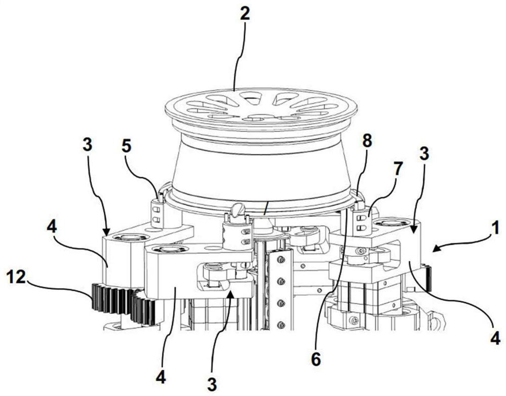
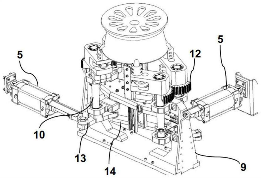
[0026] figure 1 shows a perspective view of the clamping device with clamped rim and figure 2 Another perspective view of the clamping device together with the rim is shown. The clamping device 1 can be part of a tire assembly line, not shown, in which the wheel rim 2 is conveyed to the clamping device 1 by means of a transport device, not shown, in which it is held The rim 2 can thus be fitted with a tire. For this purpose, the rim 2 must be securely clamped by the clamping device 1 in a defined position, so that the tire can be fitted successfully.

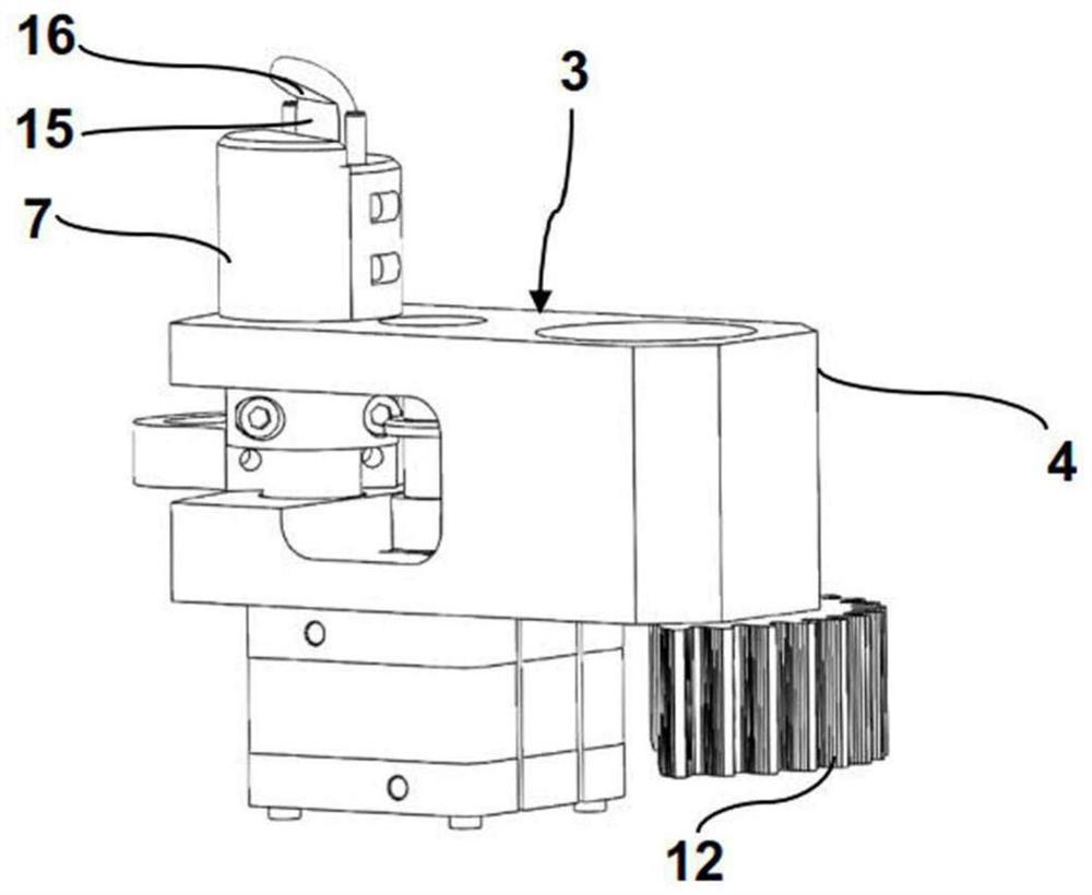
[0027] The clamping device 1 comprises four clamping elements 3 which each have a base body 4 which has, at its free end, a receptacle for a clamping arm 5 which is mounted in a non-rotatable manner. In the matrix 4. The rim 2 rests on a placement surface 6 formed by placement elements 7 . The rim 2 is clamped by clamping pins 8 protruding from the placement surface 6 , which terminate in clamping arms 5 . The clamping ar...


PUM


Abstract

In a device (1) for clamping a rim (2) of a vehicle wheel, at least four clamping elements (3) are provided which can be moved with respect to the rim (2) and comprise clamping arms (5) and support elements (7) having support surfaces (6). A rim flange of the rim (2) can be placed on the support surfaces. The clamping arms (5) are rotatably mounted, about their longitudinal axis, in the clamping elements (3), and have clamping fingers (8) at the end that protrude beyond the support surfaces (6), which fingers have clamping surfaces which can be brought into clamping contact with the placeable rim flange.

Description

technical field [0001] The invention relates to a device for clamping the rim of a wheel, said device having four clamping elements comprising a support element and a clamping arm rotatable about its longitudinal axis, said clamping arm Clamping pins with the edge of the rim that clamp the rim. Background technique [0002] In order to fit the tire onto the rim of the wheel by means of the assembly machine, it is necessary to position the wheel firmly on the table of the assembly machine. The holding force to be used here must have such a magnitude that the wheel is held securely against the resulting mounting force. The rim is clamped by the jaws, wherein the axis of the rim is substantially vertical. The tire is placed obliquely on the clamped rim, wherein the shoulder part of the tire is held by the bracket at the level of the lower rim edge. The surrounding tool first pushes the lower first tire bead onto the upper rim edge. The second tire bead is then pushed over t...

Claims


Application Information

Patent Timeline
Patent Type & Authority Applications(China)
IPC IPC(8): B60B30/06
CPCB60B30/06B60C25/0542B60C25/0539B60C25/0521B60C25/0503B60C25/0536
Inventor A.佩内尔特M.奥特威恩M.罗加拉
Owner SCHENCK ROTEC GMBH
Why Eureka
Try Eureka