Pool filtering device
A technology of filtering device and water pool, which is applied in the configuration of water supply pool, water supply device, water saving, etc., can solve the problems of no power supply and large power consumption.
- Summary
- Abstract
- Description
- Claims
- Application Information
AI Technical Summary
Problems solved by technology
Method used
Image

Examples
Embodiment 1
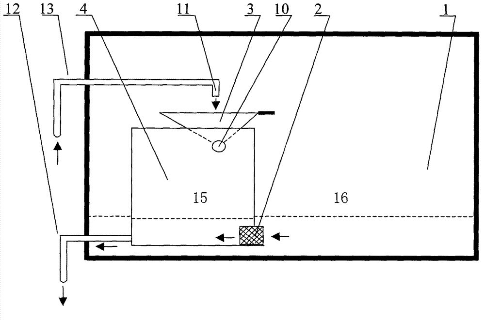
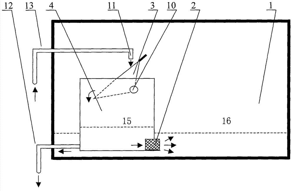
[0019] Embodiment one: if figure 1 The shown water receiving tank 4 is installed in the pool 1, and the turning tank 3 is installed on the water receiving tank 4, and the cross section of the turning tank 3 is triangular. The water outlet 11 of pool 1 water inlet pipe 13 is to the water outlet 11 of pool 1 water inlet pipe 13 tops, tap water flows into the water outlet 11 of water inlet pipe 13 and turns over groove 3. One end of the water receiving tank 4 is connected to the water outlet pipe 12 of the pool 1, and the water outlet pipe 12 is connected to the residential water pipe. A filter layer 2 is installed between the other end of the water receiving box 4 and the pool 1 . When turning over the tank 3 to store water, the water level 16 of the pool 1 is higher than the water level 15 of the water receiving tank, and the water passes through the filter layer 2 in the direction of the arrow. After being filtered by the filter layer 2, the impurities of the water remain in ...
Embodiment 2
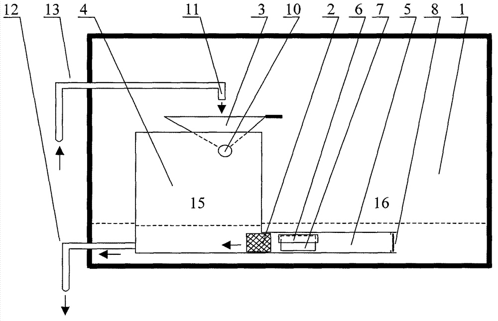
[0020] Embodiment two: if image 3 , Figure 4 The other end of the shown water receiving tank 4 is connected to the water inlet tank 5, a filter layer 2 is installed between the water receiving tank 4 and the water inlet tank 5, and the side of the water inlet tank 5 is equipped with a check valve 6, a check valve 8, and a check valve 6 can be opened in the water inlet tank 5, and the one-way valve 8 can be opened to the outside of the water inlet tank 5. When turning over the tank 3 to store water, the water level 16 of the pool 1 was higher than the water level 15 of the water receiving tank, and the check valve 6 of the water inlet tank 5 was opened inwardly, and the check valve 8 of the water inlet tank 5 other ends was closed. The water flows into the water inlet tank 5 through the one-way valve 6 of the water receiving tank 5 in the direction of the arrow, and flows into the water receiving tank 4 through the filter layer 2. Residential plumbing. Such as Figure 5 ,...
Embodiment 3
[0021] Embodiment 3: The above-mentioned water inlet tank 5 is installed with check valve 6 and check valve 8. The purpose is to keep the impurities in the filter layer 2 away from the inlet 7 of the water inlet tank 5, and prevent impurities from flowing into the filter layer 2 through the inlet 7 again. However, the pool 1 is connected to the inlet 7 and the one-way valve 8. For a long time, impurities will flow into the filter layer 2 through the inlet 7 again. Such as Figure 7 As shown, one end of the water inlet box 5 is connected to the filter bag 9, and a one-way valve 8 is installed between the water inlet box 5 and the filter bag 9. Impurities in the filter layer 2 are flushed out through the one-way valve 8 to the filter bag 9 and retained in the filter bag 9 . The rest are the same as the above-mentioned embodiment.
PUM
 Abstract
Description
Claims
Application Information
 - R&D
- Intellectual Property
- Life Sciences
- Materials
- Tech Scout
- Unparalleled Data Quality
- Higher Quality Content
- 60% Fewer Hallucinations
Browse by: Latest US Patents, China's latest patents, Technical Efficacy Thesaurus, Application Domain, Technology Topic, Popular Technical Reports.
© 2025 PatSnap. All rights reserved.Legal|Privacy policy|Modern Slavery Act Transparency Statement|Sitemap|About US| Contact US: help@patsnap.com