
Eyelet embroiderer

An embroidery machine and hole-drilling technology, which is applied to embroidery machines, embroidery machine mechanisms, automatic control embroidery machines, etc., can solve the problems of slow cutting speed, unclean cutting surface, and low punching efficiency, and achieve high cutting speed , Ensure cleanliness, improve drilling efficiency and drilling quality

Active Publication Date: 2014-02-19
ZHEJIANG XINSHENG SEWING EQUIP
View PDF7 Cites 11 Cited by
  • Summary
  • Abstract
  • Description
  • Claims
  • Application Information

AI Technical Summary

Problems solved by technology

Its defect is that the cutting surface is not clean and the cutting speed is slow
[0003] In addition, in the prior art, the cutter bar of the engraved embroidery machine is driven by the upper and lower driving mechanism to drive the cutter head to move up and down to complete the punching action, so the punching efficiency is low and the punching quality is not high

Method used


Image

  • Eyelet embroiderer
  • Eyelet embroiderer
  • Eyelet embroiderer

Examples


Embodiment Construction

[0028] Combine below Figure 3 to Figure 11 Examples of the present invention will be described in detail.

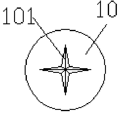
[0029] An engraved embroidery machine includes a knife bar 1, a knife head 10 is provided at the bottom of the knife bar, and a knife edge portion 101 is provided at the head end of the knife head, and the knife bar 1 is connected with a knife bar driving structure. A needle plate 2 is provided below the knife head 10, and a needle plate hole 20 is arranged on the needle plate 2. The cloth 4 is placed on the needle plate 2. into the needle plate hole 20. Wherein, in order to prevent the cloth from being rolled into the needle plate hole 20 , the knife bar 1 is provided with a cloth pressing structure, and the needle plate hole 20 is provided with a filling seat 3 .

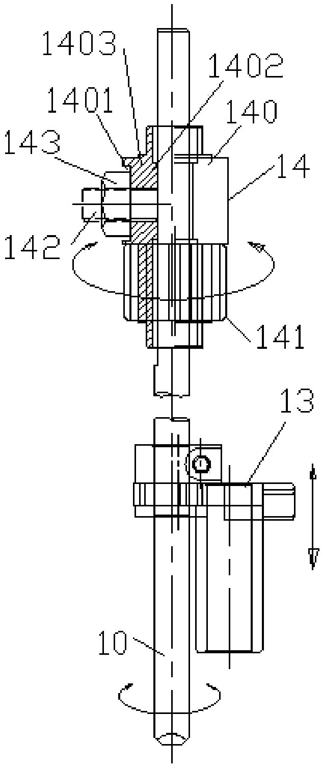
[0030] Such as Figure 3 to Figure 5 In the shown cutter bar drive structure, the cutter bar 1 is provided with an up and down drive mechanism 13 above the cutter head 10, and the cutter bar 1 is provide...


PUM


Abstract

The invention discloses an eyelet embroiderer. The eyelet embroiderer comprises a cutter bar. The bottom of the cutter bar is provided with a cutter head. The top end of the cutter head is provided with a cutting edge part. The cutter bar above the cutter head is provided with upper and lower driving mechanisms. The cutter bar above the upper and lower driving mechanisms is provided with a rotation driving mechanism. The cross section of the cutting edge part is rhombic. An angle of the cutting edge part in a width direction is in a range of 20-90 degrees and an angle of the cutting edge part in a thickness direction is in a range of 5-20 degrees. The eyelet embroiderer is provided with the rotation driving mechanism except the upper and lower driving mechanisms and thus the cutter bar drives the cutter head to punch upward and downward and to carry out rotation cutting. The angle of the cutting edge part in the thickness direction is in a range of 5-20 degrees so that cutting-off efficiency is improved and the angle of the cutting edge part in the width direction is in a range of 20-90 degrees so that eyelet width is adjusted easily and cutting-off efficiency is improved. The eyelet embroiderer improves a cutting-off rate, guarantees cut surface cleanliness and obviously improves punching efficiency and punching quality.

Description

technical field [0001] The invention relates to an engraved embroidery machine. Background technique [0002] Such as figure 1 with figure 2 As shown, the cutting edge portion 101 of the carving machine cutting head 10 in the prior art has a cross-conical structure. The disadvantages are that the cutting surface is not clean and the cutting speed is slow. [0003] In addition, in the prior art, the cutter bar of the engraved embroidery machine is driven by the upper and lower driving mechanism to drive the cutter head to move up and down to complete the punching action, so the punching efficiency is low and the punching quality is not high. Contents of the invention [0004] The technical problem to be solved by the present invention is to provide a hole-engraving embroidery machine, which can improve punching efficiency and punching quality. [0005] In order to solve the above-mentioned technical problems, the present invention adopts the following technical scheme:...

Claims


Application Information

Patent Timeline
Patent Type & Authority Applications(China)
IPC IPC(8): D05C7/04
Inventor 王海江方狄永余立科
Owner ZHEJIANG XINSHENG SEWING EQUIP
Learn More