
Driving power device of ballast type LED lamp

A technology of LED lamps and driving power, applied in the direction of lamp circuit layout, electric light sources, lighting devices, etc., can solve problems such as damage to other LED lamps

Pending Publication Date: 2014-02-12
李顺华
View PDF5 Cites 7 Cited by
  • Summary
  • Abstract
  • Description
  • Claims
  • Application Information

AI Technical Summary

Problems solved by technology

However, the driving power of the LED lights in the prior art is short-circuited due to the damage of a certain LED due to its own quality, and its original voltage drop is passed on to other LED lights, which will cause other LED lights to also fail due to overvoltage. damage

Method used


Image

  • Driving power device of ballast type LED lamp
  • Driving power device of ballast type LED lamp
  • Driving power device of ballast type LED lamp

Examples


Embodiment Construction

[0036] The present invention will be described in further detail below in conjunction with the accompanying drawings.

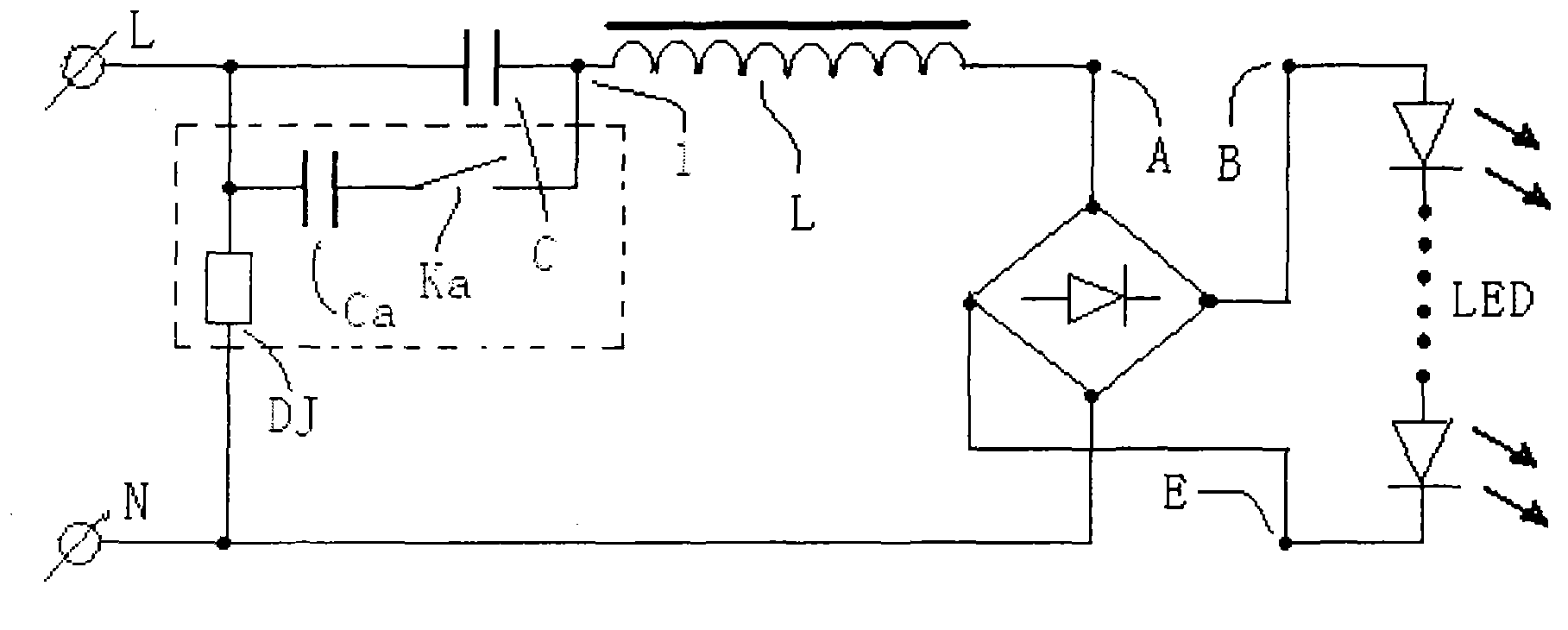
[0037] see figure 1 , the schematic diagram of the circuit structure of the driving power supply of the ballast LED lamp of the present invention, the two ends (L terminal and node 1) of the shown capacitor (C) are connected with a routing capacitor (Ca) and switch (Ka) composed of series circuit, by figure 1 It can be seen that under the rated input voltage, the capacity of the inductance ballast (L) series capacitor is (C). Connected with a circuit device (DJ) that drives the state transition of the switch (Ka) when the input voltage changes.

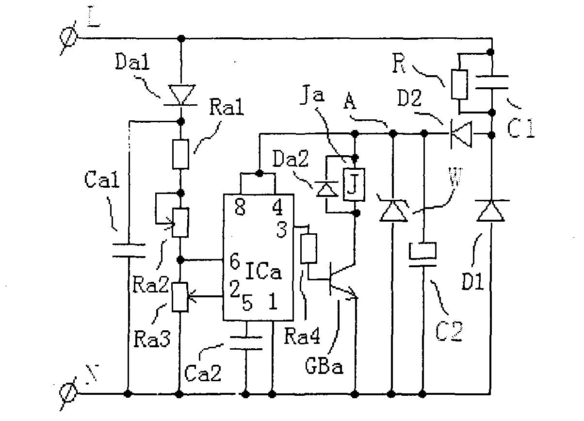
[0038] figure 2 Shown is a schematic diagram of the circuit structure of the device part of the switch (Ka) state conversion circuit device (DJ). The figure shows the power supply circuit, the sampling circuit, the driving signal circuit, the driving circuit, the execution circuit of the state conversion of the ...


PUM


Abstract

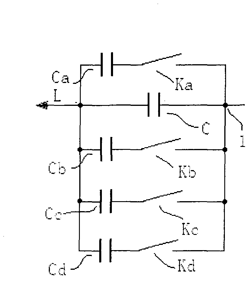
The invention discloses a driving power device of a ballast type LED lamp. The driving power device comprises a capacitor (C) and a low-consumption inductive ballast (L). The driving power device of the ballast type LED lamp is characterized in that the two ends (the L end and a node 1) of the capacitor (C) are at least connected with a series circuit which is composed of a routing capacitor (Ca) and a switch (Ka), the power input ends (the L end and the N end) of the driving power device of the ballast type LED lamp are further in parallel connection with a circuit device (DJ) which drives the state of the switch (Ka) to be converted when input voltages change. The driving power device of the ballast type LED lamp has the advantages that the purpose that a driving power source of the ballast type LED lamp is within a wide input voltage range (like 160V-250V) is achieved, the currents of the LED lamp are kept basically constant, and the driving power source of the ballast type LED lamp is made to be an ideal driving power source of the LED lamp.

Description

technical field [0001] The invention relates to a driving power supply for a solid-state light-emitting lamp, more specifically, to a driving power supply device for a ballast-type LED lamp. Background technique [0002] LED semiconductor lighting is a strategic emerging industry that the State Council has accelerated to cultivate and develop. Recently, the Ministry of Science and Technology compiled the "Twelfth Five-Year Special Plan for the Development of Semiconductor Lighting Technology". In the application technology research of the key tasks of the special plan, it was proposed to develop high-efficiency, low-cost, and highly reliable LED drive power. This illustrates the importance of LED drive power in the technical field of semiconductor lighting applications. [0003] At present, the LED drive power supply mainly uses the AC 220V mains to supply the load after rectification and inversion. The most commonly used rectification method is a rectification bridge compo...

Claims


Application Information

Patent Timeline
IPC IPC(8): H05B37/02
Inventor 李顺华
Owner 李顺华
Learn More