
Power Grid Compensation System and Its Control Method

A compensation system and power grid technology, applied in reactive power compensation, reactive power adjustment/elimination/compensation, AC network load balancing, etc., can solve problems such as large switching frequency fluctuations, low steady-state output accuracy, and compensation. Achieve the effect of optimizing the grid power structure, improving the operating conditions of the grid, and improving the economy

Active Publication Date: 2016-03-02
BYD CO LTD
View PDF6 Cites 0 Cited by
  • Summary
  • Abstract
  • Description
  • Claims
  • Application Information

AI Technical Summary

Problems solved by technology

The reactive power compensator or power filter of the ordinary three-phase four-leg inverter cannot properly deal with the voltage unbalance and harmonic Therefore, it cannot adapt to the current increasingly complex grid environment and power demand
At the same time, during operation, due to load changes, grid fluctuations, losses and other factors, the DC side capacitor voltage will fluctuate, and the DC side voltage stability directly affects the compensation effect
[0005] The disadvantages of the existing technology are that the hysteresis control is used to control the switching frequency, which has large fluctuations and low steady-state accuracy. In addition, the control between the three phases is not independent and may easily cause phase-to-phase interference; the single-cycle control is easily affected by changes in circuit working conditions. In the case of small device parameter errors, noise interference will also cause changes in the conditions of the control circuit, resulting in low accuracy of the steady-state output of the system

Method used


Image

  • Power Grid Compensation System and Its Control Method
  • Power Grid Compensation System and Its Control Method
  • Power Grid Compensation System and Its Control Method

Examples


Embodiment Construction

[0022] Embodiments of the present invention are described in detail below, examples of which are shown in the drawings, wherein the same or similar reference numerals designate the same or similar elements or elements having the same or similar functions throughout. The embodiments described below by referring to the figures are exemplary only for explaining the present invention and should not be construed as limiting the present invention.

[0023] The following disclosure provides many different embodiments or examples for implementing different structures of the present invention. To simplify the disclosure of the present invention, components and arrangements of specific examples are described below. Of course, they are only examples and are not intended to limit the invention. Furthermore, the present invention may repeat reference numerals and / or letters in different instances. This repetition is for the purpose of simplicity and clarity and does not in itself indicat...


PUM


Abstract

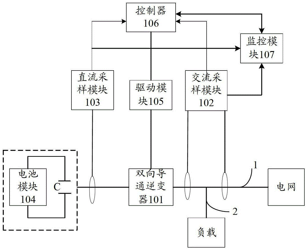
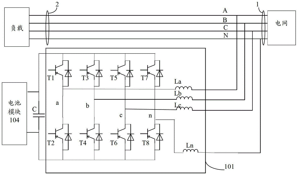
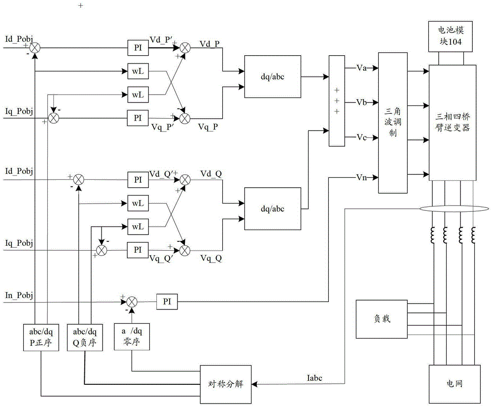
The invention provides a power grid compensating system and a control method of the power grid compensating system. Not only can precise full-range reactive harmonic wave compensation be provided for all single phases, but also power grid voltage can be balanced. The power grid compensating system comprises a bi-direction conductivity inverter, a controller, a monitoring module, a battery module and a capacitor. The method includes the following steps that states which a power grid is in is obtained according to the voltage / currents of the output end and the load end of the sampled power grid and the direct current input voltage / currents of the reverse end of the bi-direction conductivity inverter, and a control signal is generated; when the power grid is in the first state, the bi-direction conductivity inverter is controlled to conduct reversely, so that the battery module absorbs active power from the power grid and stores the active power; when the power grid is in the second state, the bi-direction conductivity inverter is controlled to conduct forward, so that the battery module performs active compensation, and the capacitor performs reactive compensation. Loads of the power grid in the first state are smaller than those of the power grid in the second state.

Description

technical field [0001] The invention relates to the technical field of power electronics, in particular to a power grid compensation system and a control method for the power grid compensation system. Background technique [0002] With the continuous development of power electronics technology, a large number of applications of nonlinear unbalanced loads have appeared. Due to the heavy active load or reactive load of a certain phase or several phases in the local power grid, the quality of the local power grid will decline, and there will be unbalanced power grid voltage, severe harmonics and excessive neutral current, resulting in increased power loss and shortened power grid. The service life of various electrical appliances. Therefore, effective measures must be taken to improve power quality. The current common measures are capacitor switching, passive filtering, dynamic reactive power compensator, active power filter, etc. [0003] Among them, the use of three-phase f...

Claims


Application Information

Patent Timeline
Patent Type & Authority Patents(China)
IPC IPC(8): H02J3/18H02J3/01H02J3/28H02J3/26
CPCY02E40/30Y02E40/40Y02E40/50
Inventor 景剑飞孙嘉品尹韶文
Owner BYD CO LTD
Learn More