Adjustment device for a motor vehicle headlamp

A technology for adjusting devices and motor vehicles, which is applied in the direction of motor vehicles, signal devices, lighting devices, etc., to achieve the effect of improving repeatability and improving the load capacity of machinery

Active Publication Date: 2014-02-12
ZKW GRP GMBH
View PDF4 Cites 1 Cited by
  • Summary
  • Abstract
  • Description
  • Claims
  • Application Information

AI Technical Summary

Problems solved by technology

The positioning of the electrically active adjusting device with respect to the axis of rotation is therefore limited at least to the distance necessary to maintain the accuracy of adjustment of the orientation of the headlight or optics-related components to the axis of rotation

Method used


Image

  • Adjustment device for a motor vehicle headlamp
  • Adjustment device for a motor vehicle headlamp
  • Adjustment device for a motor vehicle headlamp

Examples


Embodiment Construction

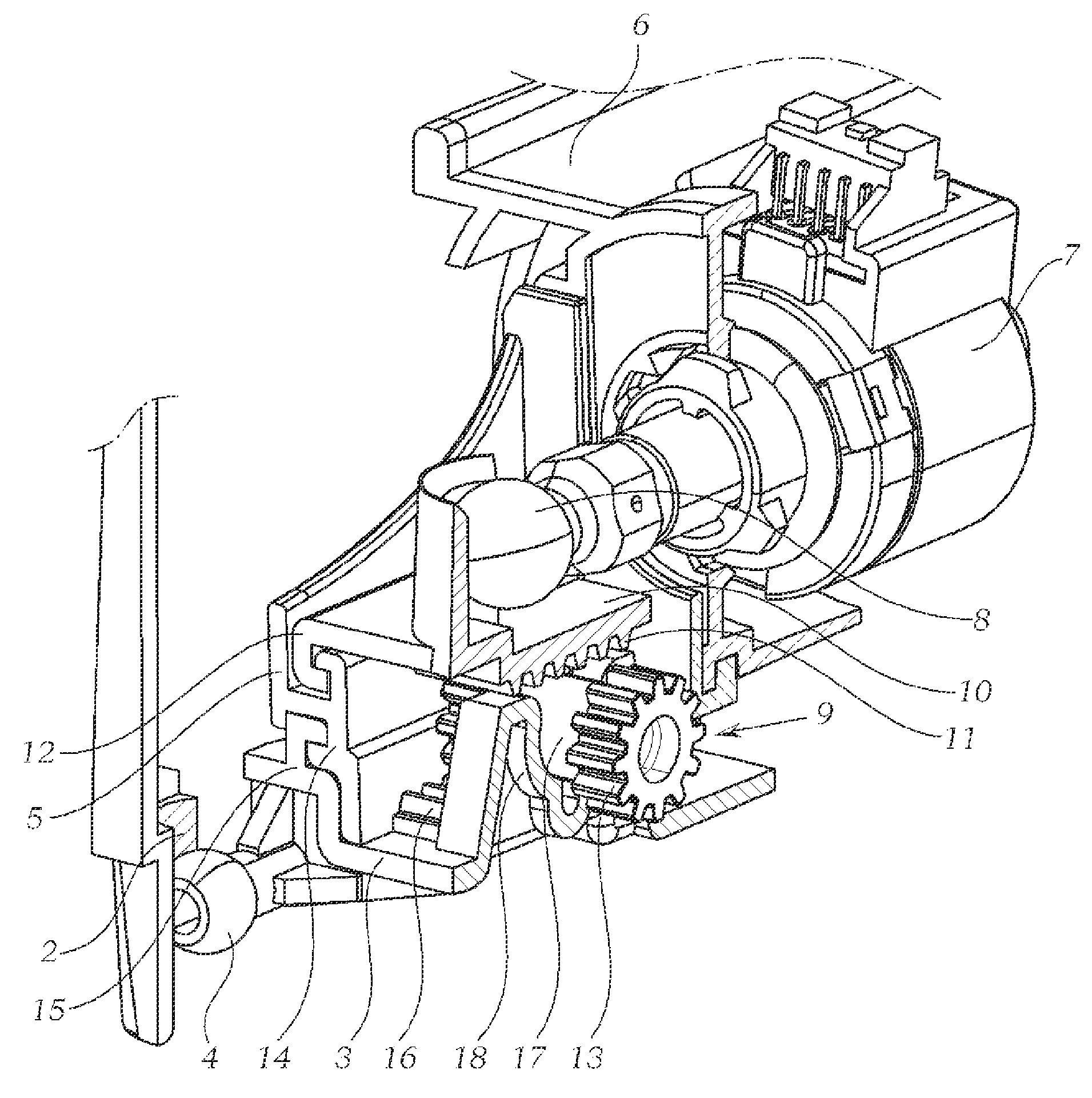
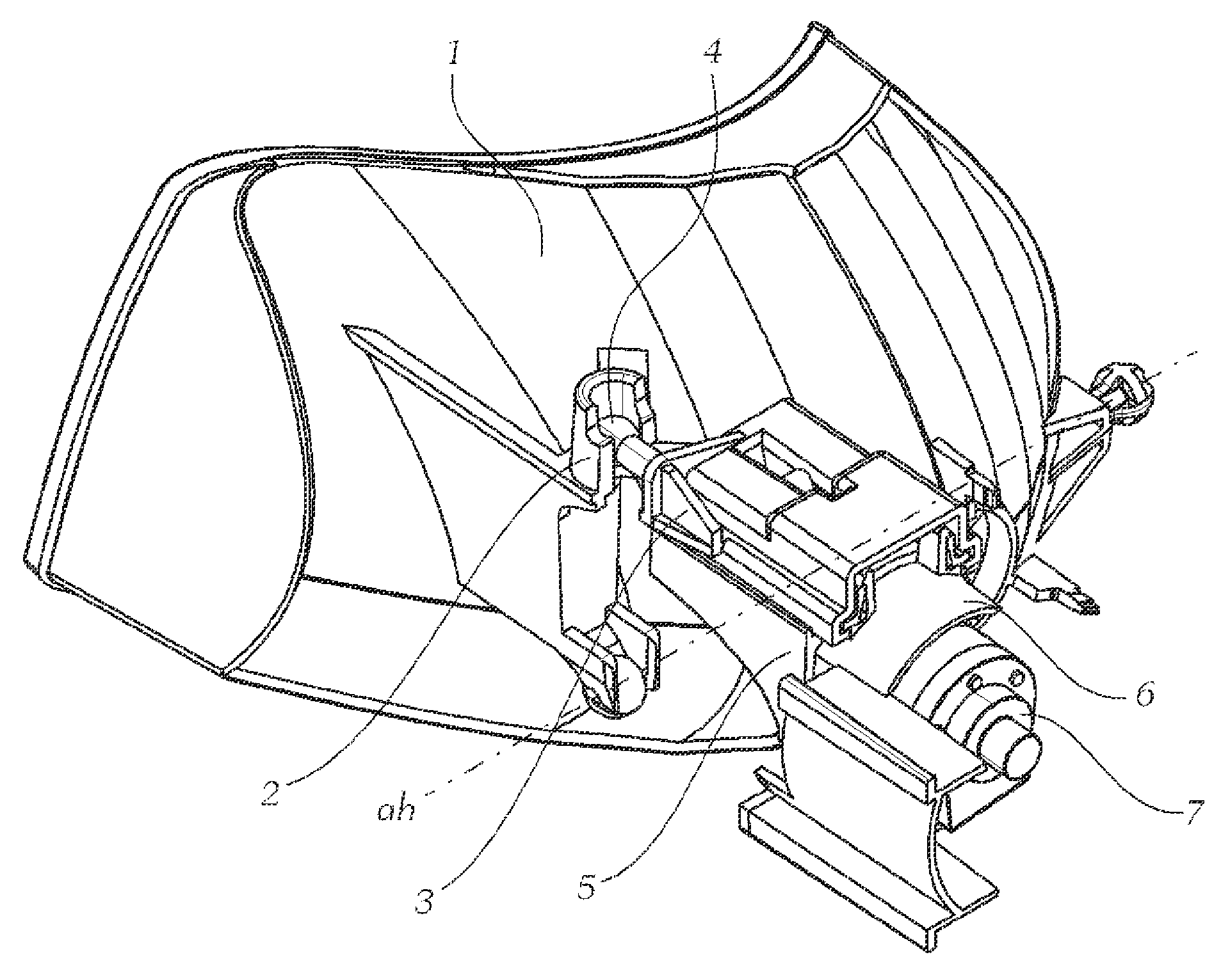
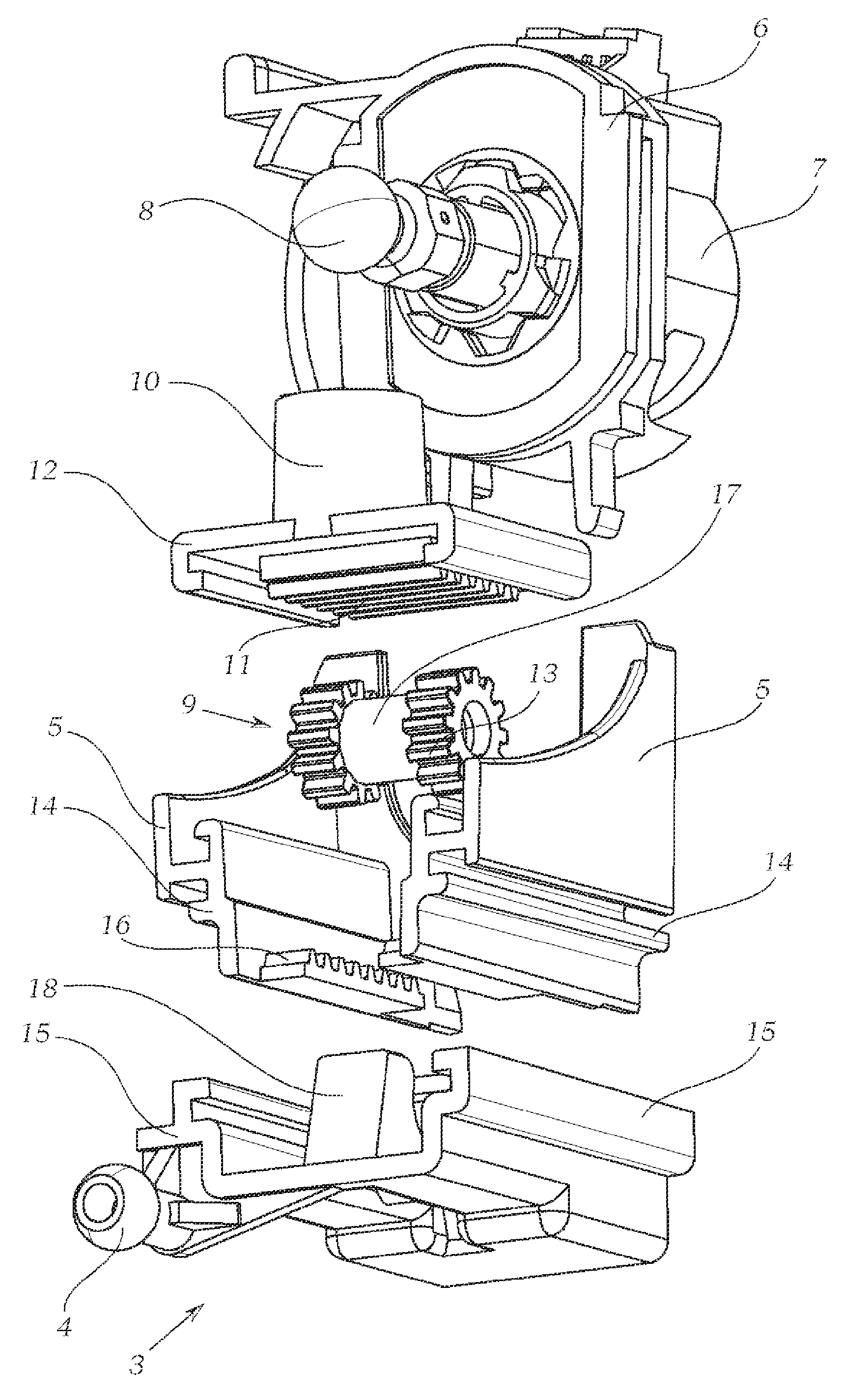
[0043] exist figure 1 shows a headlight reflector 1 , which here is an optically relevant component 1 within the meaning of the invention, and a non-limiting embodiment of the adjusting device according to the invention can be seen (see also Figure 2 to Figure 5 ). The viewing direction is here from below. Reference is made here to all the descriptions provided that no other reference is made to the state of installation of the motor vehicle headlight in the motor vehicle. exist figure 1 In this case, the headlight reflector 1 has an adjusting head receptacle 2 arranged on the headlight reflector 1 , by means of which the headlight reflector 1 engages with the adjusting head 4 of the adjusting element 3 . The headlight reflector 1 is movable here about the horizontal axis ah. The adjusting head 4 protrudes into the adjusting head receptacle 2 , by means of which the adjusting head 4 is at least partially enclosed, whereby a linear movement of the adjusting head 4 is conve...


PUM


Abstract

The invention relates to adjustment device for a motor vehicle headlamp, which comprises at least one optical correlation component (1) capable of moving by means of an actuator. The drive element (8) of the actuator drives a rolling element (9) rotatably mounted in a bearing element (18) to move. The rolling element decreases the movement speed of an adjusting element (3) along the movement of the drive element (8).

Description

technical field [0001] The invention relates to an adjusting device for a motor vehicle headlight having at least one optically relevant component movable by means of an actuator. Background technique [0002] In principle, an "optics-relevant component" is to be understood as meaning any component which exerts an influence on the light distribution present in front of the motor vehicle to the extent that adjusting / pivoting / moving the component changes the light distribution. Examples of such optics-related components are a blend (component), a light source, a reflector or an entire light module. The adjustment device described here is in principle suitable for the adjustment of all these components, but first of all it is intended to be used for adjusting a reflector and in particular one or more light modules (which are preferably arranged in a holder). The optics-relevant component can be adjusted here by swiveling, for example, about an axis or moving along a predetermi...

Claims


Application Information

Patent Timeline
Patent Type & Authority Applications(China)
IPC IPC(8): F21V21/15F21W101/02F21W107/10
CPCB60Q1/076
Inventor P.巴明格
Owner ZKW GRP GMBH
Why Eureka
Try Eureka