Valve gun for a high-pressure cleaning device

A high-pressure cleaning and valve gun technology, applied in the field of valve guns for high-pressure cleaning equipment, can solve problems such as assembly difficulties, and achieve the effects of low cost, high mechanical load capacity, and convenient assembly.

Inactive Publication Date: 2018-12-21
ALFRED KARCHER GMBH & CO KG
View PDF4 Cites 0 Cited by
  • Summary
  • Abstract
  • Description
  • Claims
  • Application Information

AI Technical Summary

Problems solved by technology

This makes valve assembly difficult
In addition, the angled design of the opening of the seat element increases its flow resistance

Method used


Image

  • Valve gun for a high-pressure cleaning device
  • Valve gun for a high-pressure cleaning device
  • Valve gun for a high-pressure cleaning device

Examples


Embodiment Construction

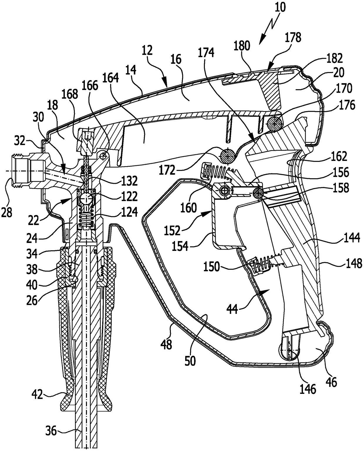
[0041] exist figure 1 An advantageous embodiment of the valve gun according to the invention is schematically shown in FIG. 1 and is assigned the reference numeral 10 as a whole. The valve gun 10 comprises a gun housing 12 which is formed in a conventional manner from a first housing half 14 and a second housing half, not shown in the drawing. The gun housing 12 has a central housing area 16 which is arranged between a front housing area 18 and a rear housing area 20 .

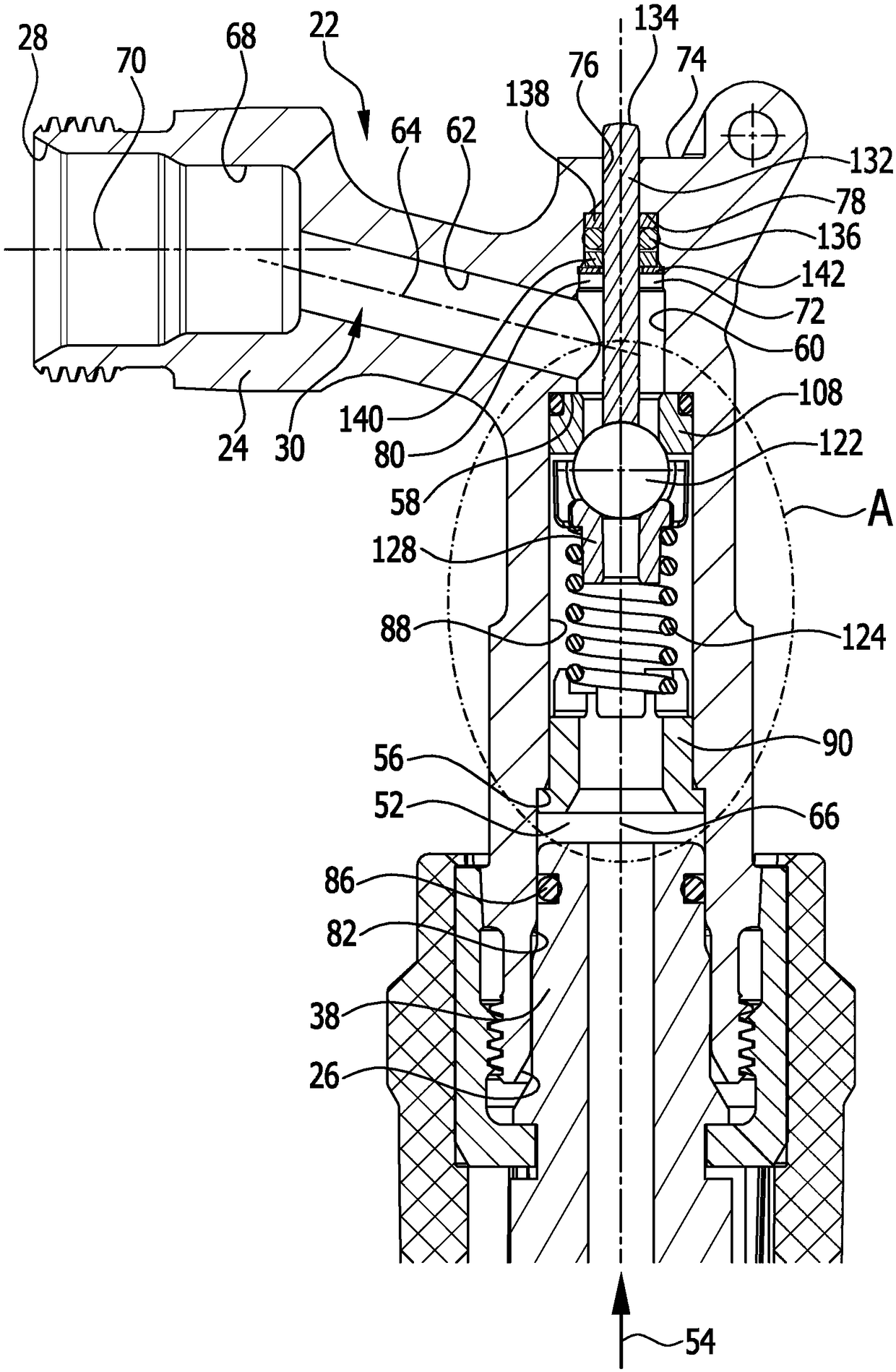
[0042] The front housing region 18 accommodates a valve 22 . The valve 22 has a valve housing 24 with an inlet 26 and an outlet 28 . The inlet 26 is in flow connection with the outlet 28 via a through-channel 30 .

[0043] In the embodiment shown, the outlet 28 protrudes from the front side 32 of the gun housing 12 . A liquid outlet line, for example a spout, can be connected to the outlet 28 . In the embodiment shown, the inlet 26 protrudes from the underside 34 of the gun housing 12 . A liquid feed lin...


PUM


Abstract

The invention relates to a valve gun (10) for a high-pressure cleaning device, comprising a valve (22) which has a valve housing (24) with a passage channel (30) that extends from an inlet (26) to anoutlet (28) and has a first channel section (52) with a first narrowed diameter section (56) arranged at a distance from the inlet (26), said narrowed diameter section being equipped with a spring holder (90). A valve seat element (108) is arranged in the first channel section (52) at a distance from the first narrowed diameter section (56), said valve seat element forming a valve seat (110), anda closing element (122) lies on the valve seat (110) in a closed position and can be acted upon by a closing force by means of a closing spring (124) supported on the spring holder (90). The closing element (122) can be moved into an open position by moving a valve tappet (132). The aim of the invention is to develop the valve gun (10) such that the valve gun can be produced and assembled less expensively. This is achieved in that the first channel section (52) is designed as a rectilinear, cylindrical, continuous valve receiving region (88) in the region from the first narrowed diameter section (56) to the valve seat element (108), and the spring holder (90) has a press-in region (94) which can be pressed into the valve receiving region (88).

Description

technical field [0001] The invention relates to a valve lance for a high-pressure cleaning device for the controlled delivery of cleaning fluid, the valve lance having a valve with a valve housing, the valve housing having a through-channel extending from an inlet to an outlet, the through-channel having a first a channel section, the first channel section has a first diameter constriction arranged at a distance from the inlet, on which a spring support is arranged, wherein in the first channel section with the first diameter The narrowing is arranged at a distance from a valve seat element, which forms a valve seat, wherein the closing body bears against the valve seat in the closed position and can be acted upon with a closing force by a closing spring supported on a spring support. , and wherein the closing body can be moved into an open position spaced apart from the valve seat by pushing a valve tappet mechanically coupled to the trigger lever. Background technique [...

Claims


Application Information

Patent Timeline
Patent Type & Authority Applications(China)
IPC IPC(8): B05B1/30B08B3/02B05B9/01B05B12/00F16K31/52
CPCB05B1/302B05B9/01F16K31/52B08B3/028B05B12/0026
Inventor 马丁·埃费尔丹尼尔·克内德勒拉尔夫·赛特丹尼尔·马诺乔本杰明·魏瑟沃尔夫冈·霍尔茨瓦特克里斯多佛·布罗伊尔
Owner ALFRED KARCHER GMBH & CO KG
Why Eureka
Try Eureka