
Rotary compressor

A technology of rotary compressor and compression mechanism, which is applied in the direction of rotary piston/oscillating piston pump components, mechanical equipment, machines/engines, etc., which can solve the problem of affecting the cooling or heating effect, increasing wear, reducing service life, etc. problem, achieve the effect of improving oil spit phenomenon and reducing oil particles

Active Publication Date: 2014-02-12
GUANGDONG MEIZHI COMPRESSOR
View PDF9 Cites 5 Cited by
  • Summary
  • Abstract
  • Description
  • Claims
  • Application Information

AI Technical Summary

Problems solved by technology

When the compressor is running for a long time or at high speed, the oil will be discharged out of the compressor together with the high-temperature and high-pressure gaseous refrigerant, resulting in insufficient lubrication of the compression parts, which will increase the compressor load and affect the cooling or heating effect. Increased wear and reduced service life

Method used


Image

  • Rotary compressor
  • Rotary compressor
  • Rotary compressor

Examples


Embodiment Construction

[0037] Embodiments of the present invention are described in detail below, examples of which are shown in the drawings, wherein the same or similar reference numerals designate the same or similar elements or elements having the same or similar functions throughout. The embodiments described below by referring to the figures are exemplary and are intended to explain the present invention and should not be construed as limiting the present invention.

[0038] In describing the present invention, it should be understood that the terms "center", "longitudinal", "transverse", "length", "width", "thickness", "upper", "lower", "front", " Orientation or position indicated by "back", "left", "right", "vertical", "horizontal", "top", "bottom", "inner", "outer", "clockwise", "counterclockwise", etc. The relationship is based on the orientation or positional relationship shown in the drawings, and is only for the convenience of describing the present invention and simplifying the descrip...


PUM


Abstract

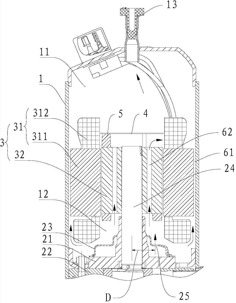
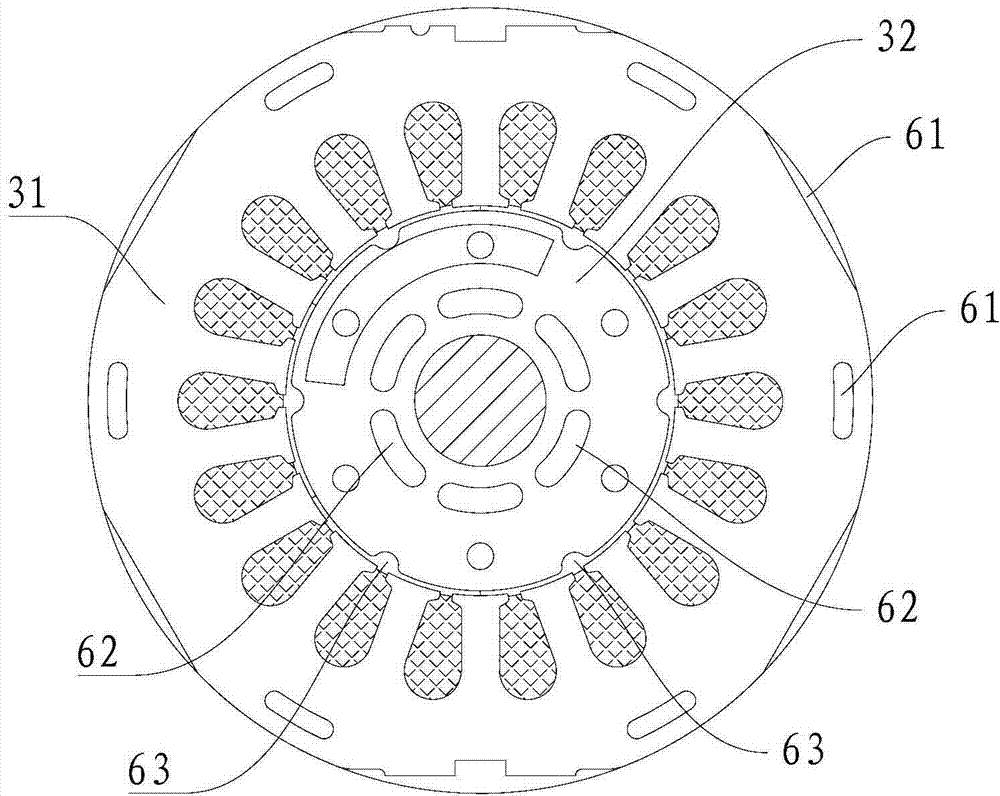
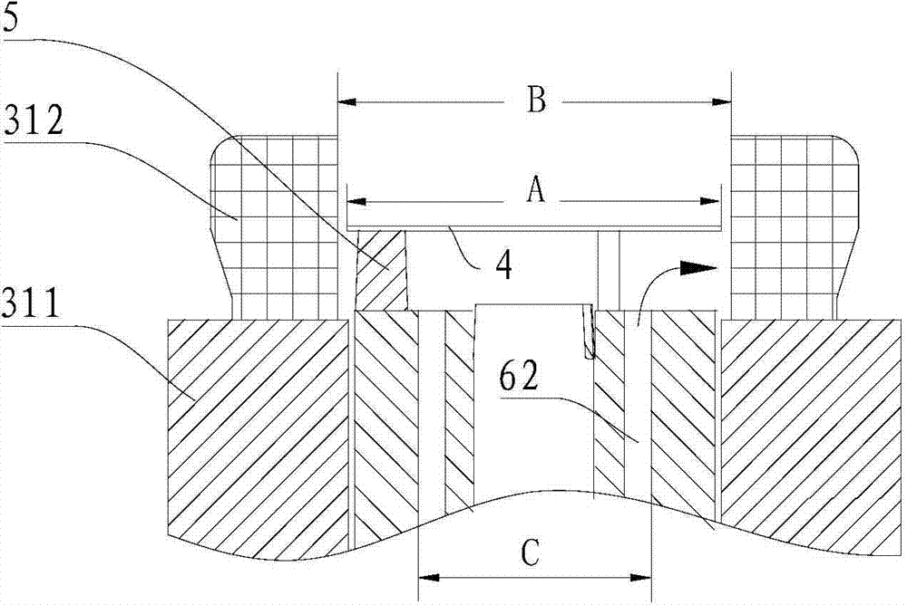
The invention discloses a rotary compressor. The rotary compressor comprises a shell, a motor, a compressing mechanism and an oil separation device, wherein the motor is arranged in the shell and separates the interior of the shell into an upper chamber and a lower chamber; the motor comprises stators and rotors; first refrigerant channels are formed in the stators and / or on the peripheries of the stators; second refrigerant channels are formed in the rotors; third refrigerant channels are defined between the rotors and the stators; the upper end of each refrigerant channel is communicated with the upper chamber and the lower end of each refrigerant channel is communicated with the lower chamber; the total areas of the cross sections of the first, second and third refrigerant channels are respectively S1, S2 and S3; S1, S2 and S3 at least satisfy one of the following relational expressions: (S2+S3) / (S1+S2+S3) is not less than 0.45; S2 / S3 is not less than 1; the compressing mechanism is arranged in the lower chamber and below the motor and is provided with a crankshaft and exhaust outlets for exhausting; the oil separation device is arranged at the top of the crankshaft or the rotors. The rotary compressor can reduce oil discharge and ensure higher energy efficiency and long service life.

Description

technical field [0001] The present invention relates to a rotary compressor. Background technique [0002] The compressor will be sealed with special lubricating oil. The lubricating oil is mainly used for the lubrication of cylinders, valve plates, bearings, crankshafts and other components, and plays the role of sealing and assisting cooling. When the compressor is running for a long time or at high speed, the oil will be discharged out of the compressor together with the high-temperature and high-pressure gaseous refrigerant, resulting in insufficient lubrication of the compression parts, which will increase the compressor load and affect the cooling or heating effect. Increase wear and reduce service life. Contents of the invention [0003] The present invention aims to solve one of the above-mentioned technical problems in the prior art at least to a certain extent. [0004] Therefore, an object of the present invention is to provide a rotary compressor, which can r...

Claims


Application Information

Patent Timeline
Patent Type & Authority Applications(China)
IPC IPC(8): F04C29/02
Inventor 刘文扬何永和
Owner GUANGDONG MEIZHI COMPRESSOR
Learn More