Vertical type winding machine for metal wires

A metal wire, winder technology, applied in the direction of conveying filamentous materials, thin material handling, transportation and packaging, etc., can solve the problems of reducing production efficiency, unstable work, increasing unloading time, etc. Ease of work effect

Inactive Publication Date: 2014-02-12
NINGBO KANGRUN MACHINERY TECH
View PDF4 Cites 3 Cited by
  • Summary
  • Abstract
  • Description
  • Claims
  • Application Information

AI Technical Summary

Problems solved by technology

The whole unloading process is very troublesome, which not only increases the time of unloading, reduces the production efficiency, but also increases the labor intensity of the operators
In addition, during the winding process of this structure, the friction plate often slips and the work is unstable.

Method used


Image

  • Vertical type winding machine for metal wires

Examples


Embodiment Construction

[0013] In order to have a further understanding and understanding of the structural features of the present invention and the achieved effects, the preferred embodiments and accompanying drawings are used for a detailed description, as follows:

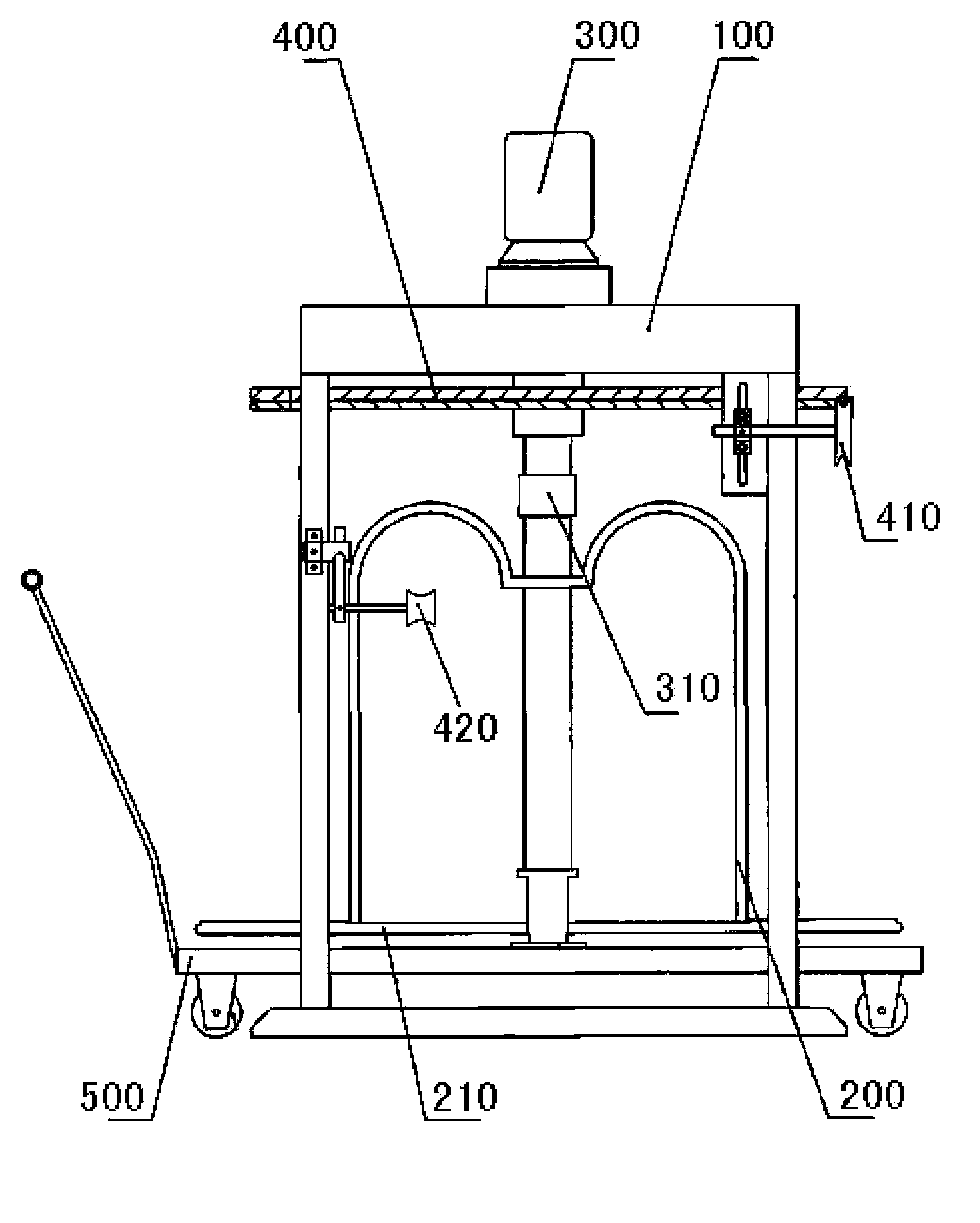
[0014] see figure 1 , a vertical winding machine for metal wire, including a bracket 100 and a winding reel 200, a driving mechanism 300, a guide plate 400 and a trolley 500, the driving mechanism 300 is arranged on the bracket 100, and the guide plate 400 is arranged on the driving mechanism 300 On the output shaft of the drive mechanism 300, a looper coupling 310 is arranged on the top of the output shaft of the driving mechanism 300, and the winding reel 200 is connected with the output shaft of the driving mechanism 300 through the looper coupling 310, and the winding reel 200 is arranged on the cart 500 on.

[0015] The driving mechanism 300 includes a torque motor and a reducer, the torque motor is connected to the reducer, and...


PUM


Abstract

The invention provides a vertical type winding machine for metal wires. The vertical type winding machine for the metal wires comprises a support, a winding plate, a driving mechanism, a guiding plate and a cart, wherein the driving mechanism is arranged on the support; the guiding plate is arranged on the output shaft of the driving mechanism; the top end of the output shaft of the driving mechanism is provided with a loop coupler; the winding plate is connected with the output shaft of the driving mechanism through the loop coupler; the winding plate is arranged on the cart. The vertical type winding machine for the metal wires has the beneficial effects that the winding plate of a product is connected with the output shaft of the driving device through a connecting shaft and the loop coupler; the winding plate is directly placed on the cart; therefore, after the completion of winding, as long as the loop coupler is lifted up to separate the winding plate from the loop coupler, the winding plate on which the metal wires are wound can be pushed out together with the cart; the whole unloading work is quite convenient.

Description

technical field [0001] The invention relates to a winding device, in particular to a winding machine for winding metal wires. Background technique [0002] At present, a horizontal winder is used for winding metal wires. Its structure usually includes a winding motor. The output shaft of the winding motor is connected with the input shaft of the reducer. The output shaft of the reducer is connected to the The reel is connected. After the winding machine finishes winding up the metal wire rod, it is necessary to unload the winding reel wound with the metal wire rod from the winder, and transport it to a transport tool, and then transport it to a designated location. The whole unloading process is very troublesome, which not only increases the time for unloading, reduces the production efficiency, but also increases the labor intensity of the operators. In addition, during the winding process of this structure, the phenomenon that the friction plate slips often occurs, and t...

Claims


Application Information

Patent Timeline
Patent Type & Authority Applications(China)
IPC IPC(8): B65H54/40B65H54/72B65H57/14
Inventor 徐新
Owner NINGBO KANGRUN MACHINERY TECH
Why Eureka
Try Eureka