marine lighting equipment

A technology for lighting equipment and lighting devices, applied in lighting and heating equipment, lighting devices, fixed lighting devices, etc., can solve problems such as inability to project light into the depths of the seabed, poor heat dissipation, inability to change and control the angle of projected light, etc. , to achieve good fish collection effect and good heat dissipation effect

Inactive Publication Date: 2015-09-23
DWTEK
View PDF4 Cites 0 Cited by
  • Summary
  • Abstract
  • Description
  • Claims
  • Application Information

AI Technical Summary

Problems solved by technology

When in use, the user uses a cable that is electrically connected to the fish-collecting light from a fishing boat to hang the fish-collecting light in the sea to emit light to attract fish. The cable hangs naturally in the sea, and the user cannot change and control the angle of its projected light. Moreover, this kind of fish-collecting light only projects light toward both sides in the hanging state, and cannot project the light effectively. To the depths of the seabed, therefore, the user must put a very long cable to make the light of this fish-collecting lamp work in the depths of the seabed, causing this kind of fish-collecting lamp to be not only inconvenient to use but also difficult to collect fish. not effectively
In addition, the overall design of this kind of fish-collecting lamp is sealed and has no heat dissipation structure, which will cause the problem of poor heat dissipation

Method used


Image

  • marine lighting equipment
  • marine lighting equipment
  • marine lighting equipment

Examples


Embodiment Construction

[0026] The present invention will be described in detail below in conjunction with the accompanying drawings and embodiments.

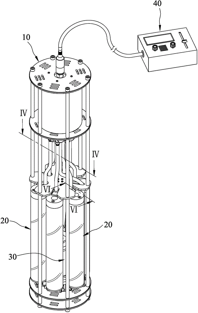
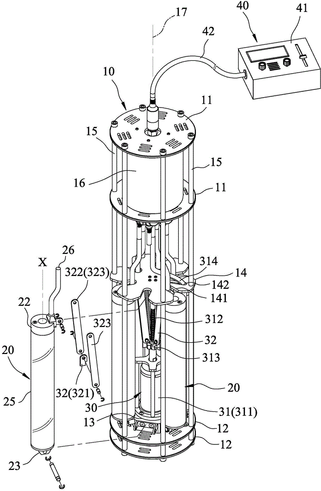
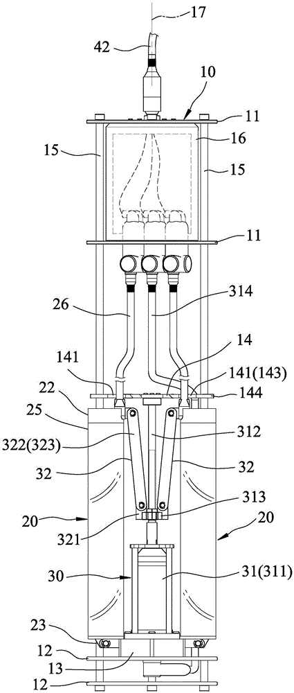
[0027] refer to figure 1 , 2 , is the first preferred embodiment of the marine lighting equipment of the present invention, and the marine lighting equipment includes: a frame 10 , several marine lighting devices 20 , a drive unit 30 , and a control unit 40 .

[0028] Such as figure 2 , 3 , 4, the frame 10 has two top plates 11 spaced apart from each other, two bottom plates 12 spaced apart from each other, a base 13 arranged on the inner bottom plate 12, and a center between the top plate 11 and the bottom plate 12. plate 14 , several supporting rods 15 connecting the top plate 11 , bottom plate 12 and the middle plate 14 , a cabin 16 arranged between the top plates 11 , and an axis 17 .

[0029] In this embodiment, the middle plate 14 has several open wire grooves 141 respectively corresponding to the marine lighting device 20, and a through ho...


PUM


Abstract

The invention discloses a submarine lighting device and submarine lighting equipment. The submarine lighting device comprises a heat dissipation column, a first extremity piece, a second extremity piece, at least one shining assembly and one sealing body; the submarine lighting equipment comprises a rack, a plurality of submarine lighting devices and a driving unit; the rack is provided with one axial line; each of the submarine lighting device is pivoted with the rack around the axial line; the driving unit is provided with a driving mechanism and a plurality of connecting assemblies; the driving mechanism is arranged on the rack; each of the connecting assembly is arranged between the driving mechanism and the each of the submarine lighting devices; the driving mechanism drives each of the submarine lighting devices via each of the connecting assemblies to move between a closer position and an expanding position relative to the rack, so as to change the inclination of each of the submarine lighting devices between the closer position and the expanding position, adjust the angle of the downward projection light ray of each of the submarine lighting devices, and generate excellent fish collection effect.

Description

technical field [0001] The present invention relates to a lighting device, in particular to a marine lighting device. Background technique [0002] Existing a kind of tube type fish collection lamp (for example No. 301131, No. 328341 of Chinese Taiwan New Patent Announcement) has a transparent tube body, two waterproof pipe sleeves that are respectively arranged on the two ends of the transparent tube body, and one is arranged on the transparent tube body. A fluorescent tube in a transparent tube body. When in use, the user uses a cable that is electrically connected to the fish-collecting light from a fishing boat to hang the fish-collecting light in the sea to emit light to attract fish. The cable hangs naturally in the sea, and the user cannot change and control the angle of its projected light. Moreover, this kind of fish-collecting light only projects light toward both sides in the hanging state, and cannot project the light effectively. To the depths of the seabed, t...

Claims


Application Information

Patent Timeline
Patent Type & Authority Patents(China)
IPC IPC(8): F21S8/00F21V29/503F21V29/56F21V31/00F21V19/02F21V29/83
Inventor 张硕文张乃仁廖家亨
Owner DWTEK
Why Eureka
Try Eureka