
closed lock

A technology of lock case and lock insertion, which is applied in building locks, cylinder locks, locks with turning keys, etc., and can solve the problems of not very wide application range, many objective requirements, and errors

Inactive Publication Date: 2015-08-12
安知政
View PDF4 Cites 0 Cited by
  • Summary
  • Abstract
  • Description
  • Claims
  • Application Information

AI Technical Summary

Problems solved by technology

It can be seen from the above that the current mechanical management lock is only convenient to use, but it cannot prevent technical opening, and its anti-theft performance is extremely low
[0003] There is also a complex internal lock cylinder, which is also the main method of unlocking with existing anti-techniques. The complex internal core makes the unlocking process very complicated to delay the time. However, the cost will increase, but the most important problem is still not solved. If it is opened, if you encounter a very powerful technology unlock thief, plus it is still aimed at a certain type of lock cylinder, it will not take long, because the design and theory will eventually have mechanical errors, as long as a trace of flaw is found, it will be the direction for them to crack
[0004] There is also an electronic combination lock, which is very safe in terms of decoding, but if someone peeps, the combination will be invalid
[0005] There are many objective requirements for electronic lock cylinders such as fingerprints and ICs, and the scope of application is not very wide.
[0006] In addition, regarding the key of the lock, the anti-matching key currently on the market is to change the surface of the key, making it a bit difficult to process, but for the gram-molding method, it is invalid, and once the key is lost, you will have to change lock

Method used


Image

  • closed lock
  • closed lock
  • closed lock

Examples


Embodiment Construction

[0071] The present invention will be further described below in conjunction with accompanying drawing:

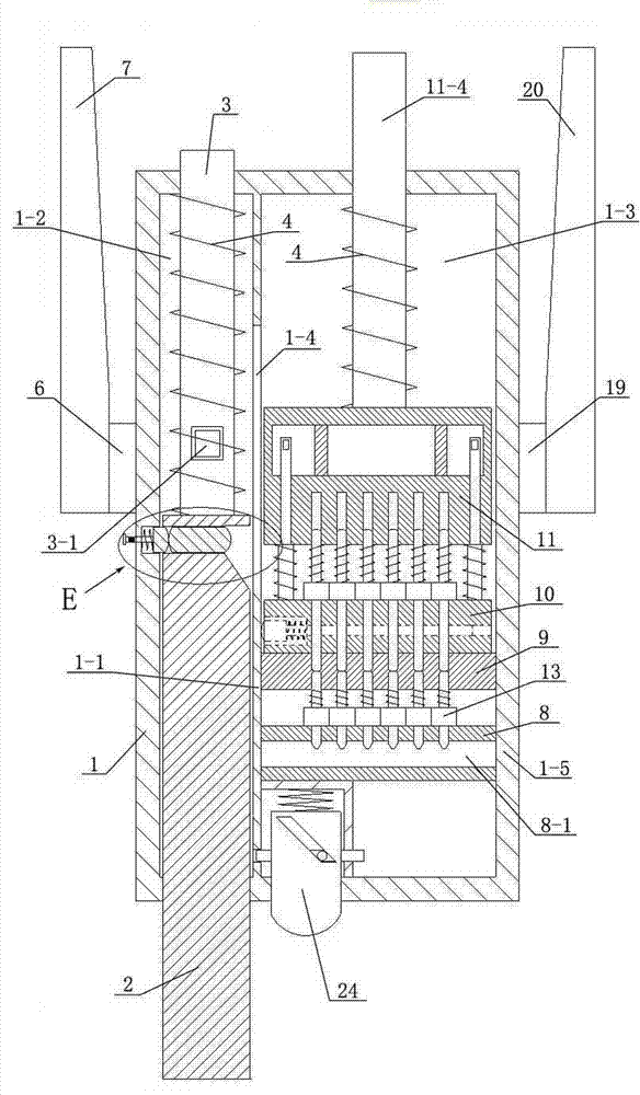
[0072] Such as Figure 1 to Figure 30 As shown, a closed lock includes a lock case 1, a lock insert, a lock cylinder and a key;

[0073] There is a partition 1-1 inside the lock case 1, and a strip-shaped through groove 1-4 is opened on the partition along the length direction of the partition; the partition 1-1 divides the interior of the lock case 1 into a left chamber 1-2 and a right chamber 1-3, the lock insert and the lock cylinder are respectively installed in the left chamber 1-2 and the right chamber 1-3 of the lock housing 1;

[0074] The lock plug includes a lock cylinder 2 and a first support rod 3 fixed at the end of the lock cylinder 2. The lock cylinder 2 and the first support rod 3 are slidingly engaged in the left chamber 1-2 of the lock case 1. The front shell of the lock case 1 The position facing the front end of the lock cylinder 2 on the wall is provi...


PUM


Abstract

The invention relates to a closed lock with a brand new structure. The closed lock comprises a lock case, a lock plug, a lock cylinder and a key. The lock plug and the lock cylinder are respectively installed on the left side and the right side of the lock case. The lock plug consists of a lock pillar and a supporting rod. The lock cylinder consists of a stop block, an isolating block, a core plate, a base and two groups of pins. The closed lock has the advantages that the design is ingenious, the structure is reasonable, reliable and durable, the closed lock is simple to operate, the safety level is high, the lock belongs to a long-time anti-opening lock, the lock can enable technical unlocking to be failed genuinely as the lock is in a full-closed state during unlocking and the lock is not in contact with the external world, and the lock is really prying-resistant and violence-resistant. Moreover, any key can be duplicated and may be lost even though the key is complex. However, the key which is provided by the invention is required to be additionally set on the site during unlocking, equivalently a code function is obtained and the problem that the key is duplicated and lost can be prevented.

Description

technical field [0001] The invention relates to a lock, in particular to a closed lock. Background technique [0002] At present, the mechanical management lock cylinder has a structure of upper and lower pins, and the supplementary beads are managed in layers, so that the thief can first apply a rotational force to the lock cylinder when performing technical opening, so that the flat beads are pressed to the side, and then they can be used again. The precision error of machining opens the marbles one by one. When all the marbles are on the same plane, the lock cylinder can be opened, thus opening the whole lock for theft. As can be seen from the above, the current mechanical management lock is only convenient to use, but cannot prevent technical opening, and its anti-theft performance is extremely low. [0003] There is also a complex internal lock cylinder, which is also the main method of unlocking with existing anti-techniques. The complex internal core makes the unlock...

Claims


Application Information

Patent Timeline
Patent Type & Authority Patents(China)
IPC IPC(8): E05B27/08E05B15/12E05B15/14E05B17/20
Inventor 安知政
Owner 安知政
Learn More