Self-adaptive magnetic field adjustment type magnetic-controlled sputter coating device and coating method thereof
A magnetron sputtering coating and magnetic field adjustment technology, which is applied in sputtering coating, ion implantation coating, vacuum evaporation coating, etc., can solve the problem of low utilization rate of planar targets and poor production continuity of magnetron sputtering coating equipment and other issues, to achieve the effect of convenient implementation, increase in quantity, and enhancement of area
- Summary
- Abstract
- Description
- Claims
- Application Information
AI Technical Summary
Problems solved by technology
Method used
Image
Examples
Embodiment 1
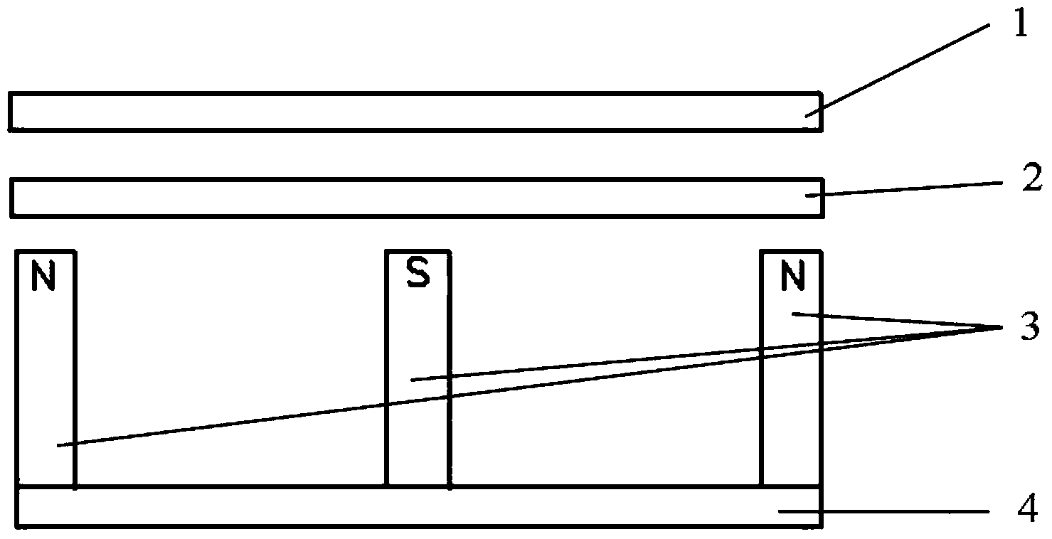
[0050] This embodiment provides an adaptive magnetic field adjustment type magnetron sputtering coating equipment, such as Figure 2a and Figure 2b As shown, it includes a substrate 1, a target 2 and a yoke 4 arranged in parallel and in sequence, and three permanent magnets 3 that are close to the target 2 and directly arranged on the yoke 4, and the magnetic poles of the adjacent permanent magnets 3 are in opposite directions. , the magnetic pole direction of the permanent magnet 3 is perpendicular to the target 2 .
[0051] The permanent magnets 3 are equidistantly arranged on the yoke 4 , and the centers of the substrate 1 , the target 2 and the yoke 4 are located on the same axis.
[0052] As other embodiments of the present invention, the number of the permanent magnets 3 may be an odd number greater than or equal to 3, all of which can achieve the purpose of the present invention and belong to the protection scope of the present invention.
[0053] An energized coil 6...
Embodiment 2
[0065] This embodiment provides an adaptive magnetic field adjustment type magnetron sputtering coating equipment, such as Figure 2a and Figure 2b As shown, it includes a substrate 1, a target 2 and a yoke 4 arranged in parallel and in sequence in the chamber, and three permanent magnets 3 that are close to the target 2 and directly arranged on the yoke 4, and the adjacent permanent magnets 3 The magnetic pole direction is opposite, and the magnetic pole direction of the permanent magnet 3 is perpendicular to the target material 2 .
[0066] The specification of the substrate 1 is 210mm×260mm, the specification of the target material 2 is 200mm×250mm×9mm, the specification of the yoke 4 is 25mm×200mm, and the specification of the permanent magnet 3 is 20mm×25mm× 70mm.
[0067] The distance between the substrate 1 and the target 2 is 68 mm, and the distance between the target 2 and the yoke 4 is 86 mm.
[0068]In this embodiment, there are three permanent magnets 3, and th...
PUM
| Property | Measurement | Unit |
|---|---|---|
| thickness | aaaaa | aaaaa |
Abstract
Description
Claims
Application Information
 - R&D
- Intellectual Property
- Life Sciences
- Materials
- Tech Scout
- Unparalleled Data Quality
- Higher Quality Content
- 60% Fewer Hallucinations
Browse by: Latest US Patents, China's latest patents, Technical Efficacy Thesaurus, Application Domain, Technology Topic, Popular Technical Reports.
© 2025 PatSnap. All rights reserved.Legal|Privacy policy|Modern Slavery Act Transparency Statement|Sitemap|About US| Contact US: help@patsnap.com


