Eureka AIR delivers breakthrough ideas for toughest innovation challenges, trusted by R&D personnel around the world.

Wire harness welding machine

A welding machine and wire harness technology, applied in welding equipment, connections, circuit/collector parts, etc., can solve the problems of uneven tinning, easy breakage and damage, and easy rotation of tin wires, so as to reduce the amount of tin and improve the Accuracy, not easy to break and damage the effect

Active Publication Date: 2014-02-05
KUNSHAN SYSTRONICS AUTOMATION TECH CO LTD
View PDF10 Cites 4 Cited by
  • Summary
  • Abstract
  • Description
  • Claims
  • Application Information

AI Technical Summary

Problems solved by technology

[0003] In order to solve the problem that the cross-section of the tin wire used in the welding of the wire harness and the connector in the prior art is circular, the tin wire is easy to rotate, the welding accuracy is low, the amount of tin is large, the tin is not uniform enough, and the tin wire is easy to break during the transfer process To solve the problem of damage, the present invention provides a wire harness welding machine with simple structure, convenient processing, improved welding accuracy, reduced tin wire usage, and reduced cost

Method used


Image

  • Wire harness welding machine
  • Wire harness welding machine
  • Wire harness welding machine

Examples


Embodiment Construction

[0015] The present invention will be further described below in conjunction with the accompanying drawings.

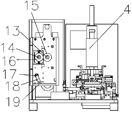
[0016] Such as Figure 1-4 As shown, a wire harness welding machine includes a base 1, a discharge rack 2, a motor 3, a welding machine body 4, jaws 5, a clamping cylinder 6, a carrier table 20, a moving frame 7 and a pushing cylinder 8, and on the base 1 is provided with a discharge rack 2, and the discharge rack 2 includes a front panel 10 and a rear panel 11, and a support shaft 9 for placing a tin wire reel is provided at the top position of the front panel 10 of the discharge 2 rack. Frame 2 rear panel 11 rear end is provided with motor 3, is provided with driving shaft 13 and driven shaft 14 between the front and rear panels of discharging rack 2, is provided with main gear 12 in the middle part of driving shaft 13, and is arranged in the middle part of driven shaft 14. There is a slave gear meshed with the main gear 12, the output shaft of the motor 3 passes th...


PUM


Abstract

The invention discloses a wire harness welding machine, which comprises a base, a material placing frame, a motor and a welding machine body. The wire harness welding machine is characterized in that the material placing frame is arranged on the base, a support shaft is arranged on the top of the material placing frame, the back end of the material placing frame is provided with the motor, the front end of the material placing frame is provided with a driving press wheel and a driven press wheel, the motor drives the driving press wheel and the driven press wheel to rotate, a carrier table is arranged at the side surface of the material placing frame, a moving frame is arranged at the back end of the carrier table and can slide along a guide rail, a clamping air cylinder is arranged on the moving frame, the clamping air cylinder controls a clamp claw to tightly clamp tin wires, a welding machine body is arranged at the back end of the moving frame, and a welding head is arranged on the welding machine body. The wire harness welding machine solves the problems that a wire harness and a connector are welded, the tin wires can easily rotate, the welding precision is low, the tin consumption is great, the tin adhesion is not uniform enough, and in addition, the tin wires can easily fracture and can be easily damaged in the processing process. The invention provides the wire harness welding machine with the advantages that the processing is convenient, the welding precision is improved, the tin wire consumption is reduced, and the cost is reduced.

Description

technical field [0001] The invention relates to a wire harness welding device, in particular to a wire harness welding machine. Background technique [0002] The current wire harness welding machine uses the HOT-BAR welding machine to directly weld the wire harness and the connector through the tin wire. When using the tin wire for welding, since the cross section of the tin wire is circular, the wire harness and the connector are connected between the two. When the tin wire is placed between them for welding, the tin wire is very easy to roll, causing welding misalignment and affecting the processing effect. At the same time, the tin wire with a circular cross-section has a large volume, which leads to a large amount of tin on each product, which increases the cost, and the entire tin surface is not uniform after tinning, which affects the welding effect. In addition, the diameter of the tin wire is very small , It is very easy to break during processing, which brings grea...

Claims


Application Information

Patent Timeline
Patent Type & Authority Applications(China)
IPC IPC(8): B23K3/06B23K3/00H01R43/02
CPCB21F15/00B23K3/063B23K3/08B23K2101/36H01R43/0235
Inventor 张晓亮胡二军
Owner KUNSHAN SYSTRONICS AUTOMATION TECH CO LTD
Why Eureka
Eureka Blog
Learn More