
Data transmission method and data transmission device

A data transmission method and data technology, applied in the field of communication, can solve problems such as low frequency diversity gain and small data transmission coverage

Inactive Publication Date: 2014-01-29
ZTE CORP
View PDF5 Cites 20 Cited by
  • Summary
  • Abstract
  • Description
  • Claims
  • Application Information

AI Technical Summary

Problems solved by technology

[0008] Aiming at the problem in the related art that the frequency diversity gain of the data transmission method is relatively low and the coverage of the data transmission is relatively small, the present invention provides a data transmission method and device to at least solve the problem

Method used


Image

  • Data transmission method and data transmission device
  • Data transmission method and data transmission device
  • Data transmission method and data transmission device

Examples


Embodiment 1

[0087] This preferred embodiment provides a data transmission method. In this preferred embodiment, the transmitting end determines the frequency domain position of the physical resource block used to transmit data by frequency hopping, and the frequency domain position is at least based on the number of subbands and the data transmission The number of times is determined.

[0088] In this preferred embodiment, the first frequency domain position of the physical resource block is determined as follows: or, n PRB S 1 ( i ) = mod [ ( n VRB + ( mod ( T Num ...

Embodiment 2

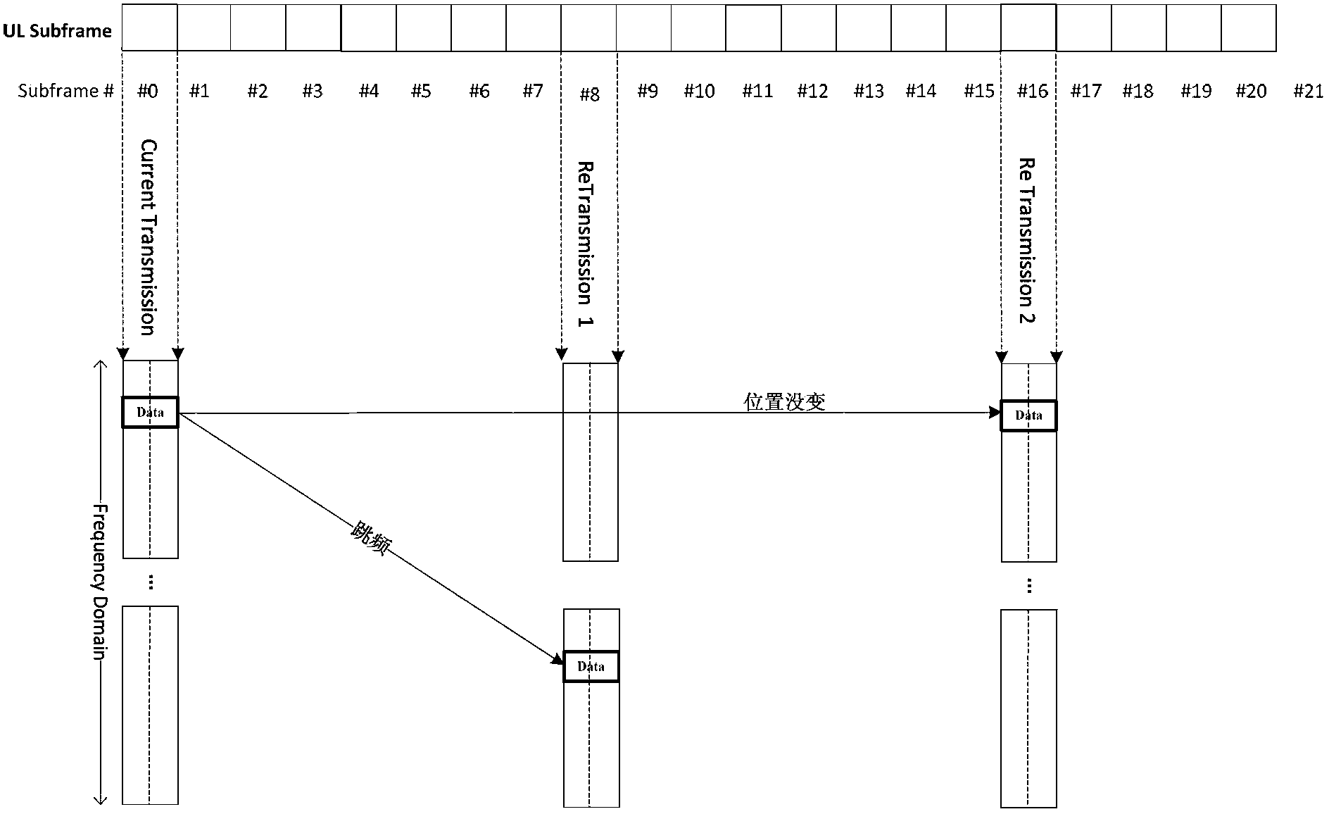
[0099] This preferred embodiment provides a data transmission method, such as figure 1 As shown, subframe 0, subframe 8, and subframe 16 are the resource positions occupied by the first transmission and retransmission of data. When frequency hopping between subframes of type 1 is used, there are only two frequency hopping positions and two frequency hopping positions It is used alternately according to the number of transmissions. Obviously, the resource position of the second retransmission is the same as that of the first retransmission. If there is a third retransmission, it will use the resource position of the first retransmission.

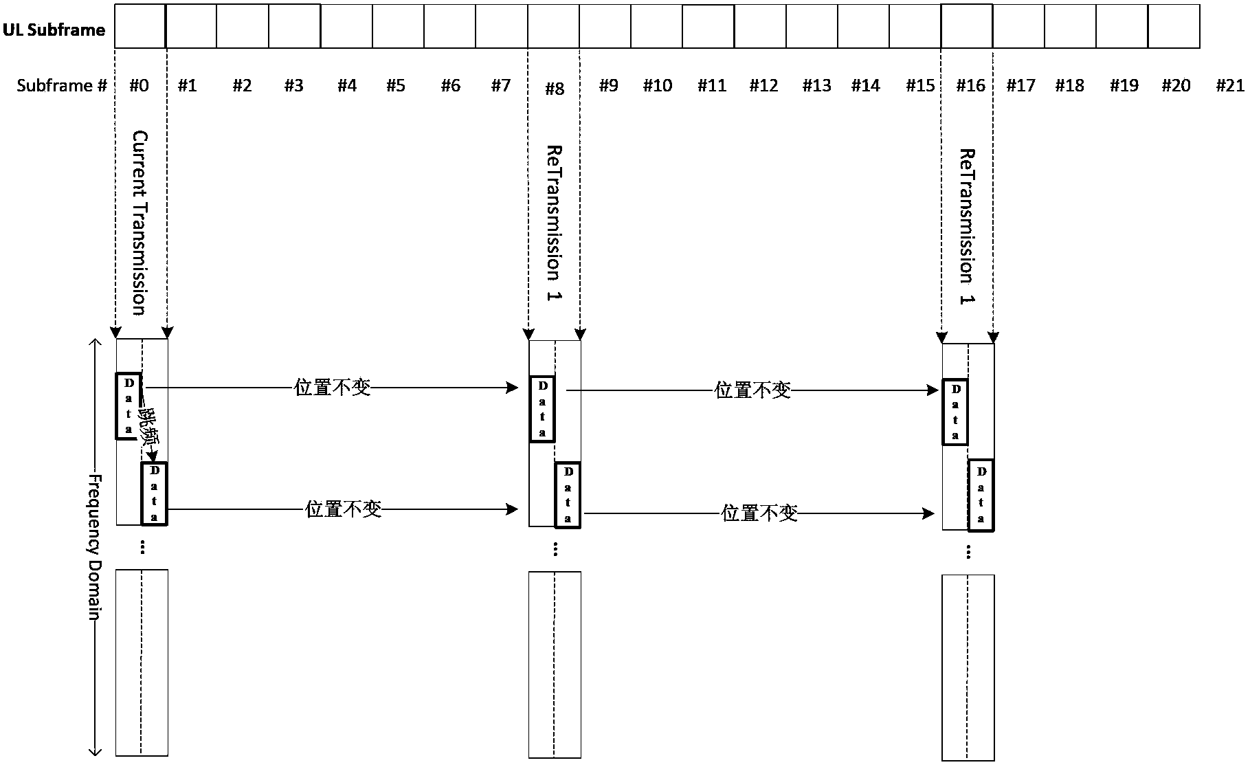
[0100] When using the enhanced type 1 inter-subframe frequency hopping, such as Figure 6 As shown, by setting the number of subbands, the number of frequency hopping positions can be increased. Different frequency hopping positions may be used for different times of transmission.

[0101] In this preferred embodiment, the frequency hopping...

Embodiment 3

[0118] The conditions of this preferred embodiment are the same as those of preferred embodiment 2, but the difference is that the frequency hopping position of the first Slot in the subframe of the first transmission or retransmission is determined according to formula 3:

[0119] n PRB S 1 ( i ) = mod [ ( n VRB + ( mod ( T Num , N sb ) ) * N RB sb ) , N RB PUSCH ...


PUM


Abstract

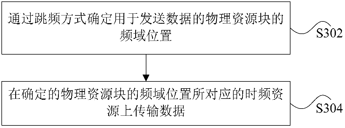
The invention discloses a data transmission method and a data transmission device. The method includes determining a frequency domain position of a physical resource block used for sending data by means of frequency hopping, wherein the frequency domain position is determined at least according to the number of sub-bands and the number of transmission times of the data; transmitting the data on time frequency resources corresponding to the determined frequency domain position of the physical resource block. By the data transmission method and the data transmission device, frequency gain of data transmission is increased.

Description

technical field [0001] The present invention relates to the communication field, in particular, to a data transmission method and device. Background technique [0002] In the Long Term Evolution (LTE for short) system, the Orthogonal Frequency Division Multiple Access (OFDMA) technology is used for the downlink, and the single carrier-frequency division multiple access is used for the uplink. SC-FDMA (Single Carrier-Frequency Division Multiple Access, referred to as SC-FDMA) technology, but due to the general use of the same frequency network, inter-cell interference (Inter-Cell Interference, referred to as ICI) increases significantly. In order to reduce the ICI, LTE adopts some anti-interference technologies, for example, downlink inter-cell interference cancellation (Inter-Cell Interference Cancellation, ICIC for short). The downlink ICIC technology is based on the relative narrowband transmit power (Relative Narrowband TX Power, RNTP) limitation of the evolved Node B (e...

Claims


Application Information

Patent Timeline
Patent Type & Authority Applications(China)
IPC IPC(8): H04B1/713H04L1/00
CPCH04B1/713
Inventor 关艳峰陈宪明罗薇袁弋非张峻峰
Owner ZTE CORP
Learn More