
Battery in-situ test method and device and battery charge system

A battery charging and detection device technology, which is applied to battery circuit devices, measuring devices, circuit devices, etc., can solve the problems of battery disconnection, failure to detect battery status in time, and normal operation of the system, etc., to achieve the purpose of prolonging the use time Effect

Active Publication Date: 2014-01-29
HUAWEI TECH CO LTD
View PDF4 Cites 31 Cited by
  • Summary
  • Abstract
  • Description
  • Claims
  • Application Information

AI Technical Summary

Problems solved by technology

[0002] At present, battery-powered electronic devices (especially mobile electronic devices, such as smartphones, tablets, laptops or portable instrument lights) are widely used in people's daily life. These electronic devices usually have battery charging and discharging control systems, Because the battery is sometimes disconnected due to faults or artificially plugged in and out, if the battery status cannot be detected in time, it will have a potential impact on the normal operation of the system

Method used


Image

  • Battery in-situ test method and device and battery charge system
  • Battery in-situ test method and device and battery charge system
  • Battery in-situ test method and device and battery charge system

Examples


Embodiment Construction

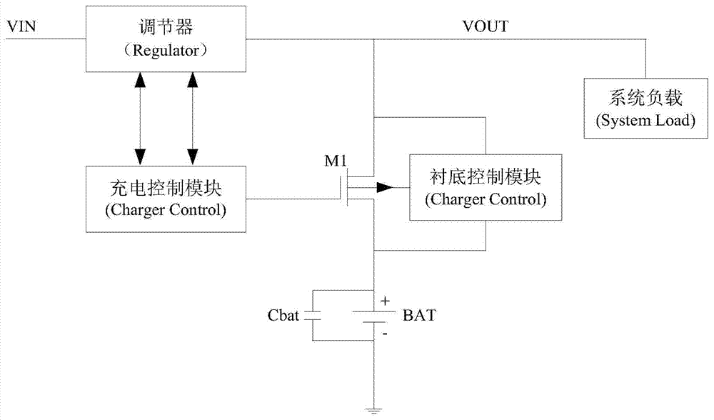
[0049] The general charging and discharging system will require the system to report the situation that the battery is not in place, so as to facilitate the timely response of the system software and hardware. figure 1A possible charging and discharging structure is shown. As shown in the figure, the structure charges the battery through the charging control module and power tube M1, and uses bat_track (battery follow) technology during the charging process, that is, the output voltage (VOUT) follows The battery voltage (VBAT) changes and maintains a certain voltage drop, that is, VOUT=VBAT+ΔV. In this structure, if the battery is pulled out during the charging process, in the absence of a battery presence detection mechanism, the charging control module will continue to charge the battery terminal, and the system load will continue to pull power, so that the battery The terminal voltage is in the state of repeated charging termination and recovery charging, causing the batter...


PUM


Abstract

An embodiment of the invention provides a battery in-situ test device. The battery in-situ test device is characterized in that a test trigger module tests charge current from a battery end and triggers a logic control module when the charge current is smaller than a preset current threshold; the logic control module shuts down the battery charge system and directs a charge-discharge balance module to charge and then discharge the battery end; during discharge operation, a test judgment module tests voltage of the battery end and judges whether the voltage of the battery end is smaller than preset test voltage or not; if yes, a battery is judged being not in situ; if not, the battery is determined being in situ. The embodiment further provides a battery charge system and a battery in-situ test method. Through the application of the embodiment, the battery can be automatically tested in situ with no external elements, and charge efficiency is unaffected during the test process.

Description

technical field [0001] The invention relates to the technical field of battery detection, and more specifically, to a battery presence detection method, device and charging system. Background technique [0002] At present, battery-powered electronic devices (especially mobile electronic devices, such as smartphones, tablets, laptops or portable instrument lights) are widely used in people's daily life. These electronic devices usually have battery charging and discharging control systems, Because the battery is sometimes disconnected due to faults or artificially plugged in and out, if the battery presence cannot be detected in time, it will have a potential impact on the normal operation of the system. Contents of the invention [0003] Embodiments of the present invention provide a battery presence detection method, device and charging system to detect whether the battery is in place. [0004] In the first aspect, a battery in-position detection device is provided, whic...

Claims


Application Information

Patent Timeline
IPC IPC(8): H02J7/00G01R19/165
CPCY02E70/40H02J7/0036
Inventor 杨洋李汇王建平王鹏飞
Owner HUAWEI TECH CO LTD
Learn More