
Array typed laser scanner

A laser scanner and array technology, applied in the field of array laser scanners, can solve the problems of no multi-beam scanning and multi-target detection laser scanners, increase the complexity of the system, etc., achieve a large scanning range, high control accuracy, The effect of high space utilization

Active Publication Date: 2014-01-29
HUAZHONG UNIV OF SCI & TECH
View PDF2 Cites 18 Cited by
  • Summary
  • Abstract
  • Description
  • Claims
  • Application Information

AI Technical Summary

Problems solved by technology

Existing laser scanners can only achieve single-beam scanning and single-target detection, and multiple laser scanners are required to achieve multi-beam scanning and multi-target detection, which will greatly increase the complexity of the system
At present, there is no laser scanner capable of multi-beam scanning and multi-target detection

Method used


Image

  • Array typed laser scanner
  • Array typed laser scanner
  • Array typed laser scanner

Examples


Embodiment Construction

[0023] The specific embodiments of the present invention will be further described below in conjunction with the accompanying drawings. It should be noted here that the descriptions of these embodiments are used to help understand the present invention, but are not intended to limit the present invention. In addition, the technical features involved in the various embodiments of the present invention described below can be combined with each other as long as they do not constitute a conflict with each other.

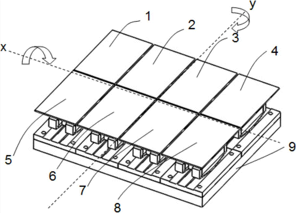
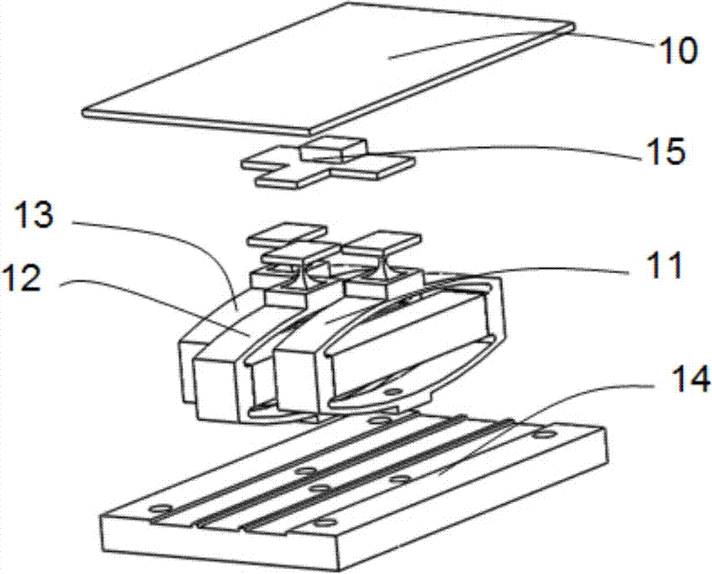
[0024] The following describes the structure of the array laser scanner provided by the present invention with the number of sub-mirrors being eight. refer to figure 1 , this example includes first to eighth sub-mirrors 1-8, a base 9, and a control drive system.

[0025] The first to eighth sub-mirrors 1 to 8 are arranged in two rows according to the same orientation, with four in each row, and are fixed on the base 9 . Among them, the first to fourth sub-mirrors 1, 2...


PUM


Abstract

The invention discloses an array typed laser scanner comprising a base, a control driving system and a plurality of auxiliary mirrors arranged in array. The auxiliary mirrors are arranged on the same direction and are fixed on the base; gaps are reserved between two adjacent auxiliary mirrors, so that the auxiliary mirrors do not touch each other when inclining to each other; the control driving system is connected with piezoelectric drivers in Ns of the auxiliary mirrors to realize open loop control of deflecting angles of reflectors. A multiple light ray scanning method is utilized to connect a plurality of small scanning fields into a big scanning field, and is capable of ensuring scanning angles and scanning frequency at the same time, each auxiliary is capable of scanning independently and multiple task detection is realized. With the array typed laser scanner, space utilization rate is greatly increased, and scanning angles are improved; the array typed laser scanner is characterized in that the array typed laser scanner is fast in driving speed, high in control accuracy, no mechanical abrasion, compact in structure, high in space utilization rate and good in stability, small in volume, light in weight, high in rigidity and is especially suitable for application of satellite and unmanned machine imaging laser radar.

Description

technical field [0001] The invention belongs to the field of light beam control, and in particular relates to an array laser scanner. Background technique [0002] Lidar is a radar system that emits laser beams to detect characteristic quantities such as the position and speed of targets. In terms of working principle, there is no fundamental difference from microwave radar: launch a laser beam to the target, then compare the received signal (target echo) reflected from the target with the transmitted signal, and after proper processing, you can get Target information, such as target distance, azimuth, height, speed, attitude, and even shape parameters, so as to detect, track and identify aircraft, missiles and other targets. Compared with microwave radar, lidar has the advantages of high resolution, clear imaging, high measurement accuracy, good concealment, strong anti-interference ability and small size. Imaging laser radar is a kind of laser radar. It can not only meas...

Claims


Application Information

Patent Timeline
Patent Type & Authority Applications(China)
IPC IPC(8): G02B26/12
CPCG02B26/12G01S7/4817G01S7/4972G01S17/42G02B26/105
Inventor 陈巍赖建军陈四海罗栋李鹏赵灿兵
Owner HUAZHONG UNIV OF SCI & TECH
Learn More