Clock test circuit

A technology for testing circuits and clock circuits, which is applied in the direction of measuring electricity, measuring electrical variables, electronic circuit testing, etc. It can solve the problems of inaccurate test results and difficulty for testers to distinguish the decimal point of 0.3 seconds.

Inactive Publication Date: 2014-01-22
HONG FU JIN PRECISION IND (SHENZHEN) CO LTD +1
View PDF0 Cites 4 Cited by
  • Summary
  • Abstract
  • Description
  • Claims
  • Application Information

AI Technical Summary

Problems solved by technology

However, if the deviation between the time generated by the clock circuit and the standard time is 2.3 seconds, it is difficult for testers to distinguish 0.3 seconds behind the decimal point
Therefore, the test results may not be accurate

Method used


Image

  • Clock test circuit
  • Clock test circuit

Examples


Embodiment Construction

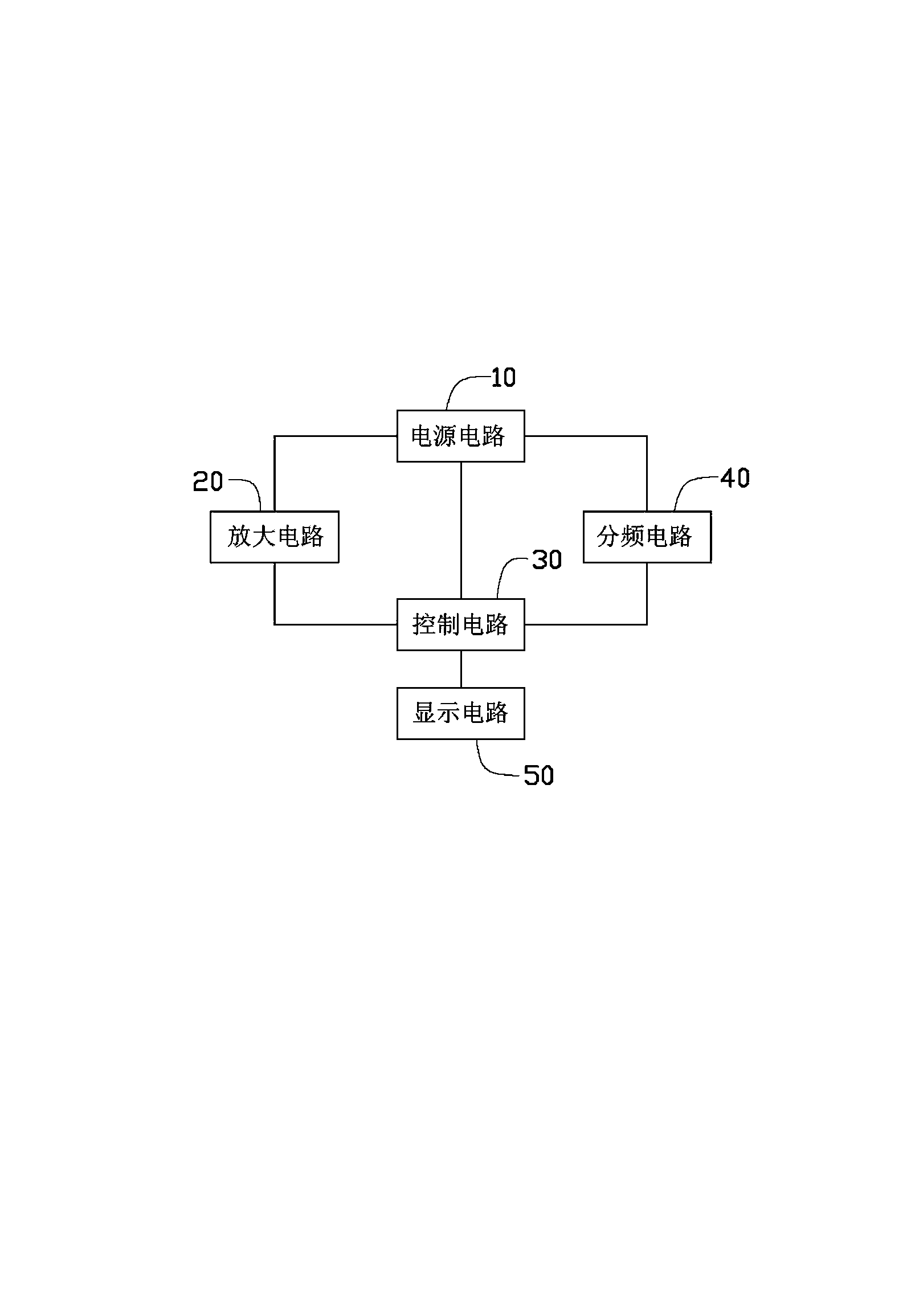
[0014] Please refer to figure 1 , the clock test circuit of the present invention is used for testing whether a clock circuit is qualified, and the preferred embodiment of this clock test circuit comprises an amplifying circuit 20, a frequency dividing circuit 40, a control circuit 30, a display circuit 50 and a The circuit 20 , the frequency dividing circuit 40 and the control circuit 30 provide the power supply circuit 10 with an operating voltage.

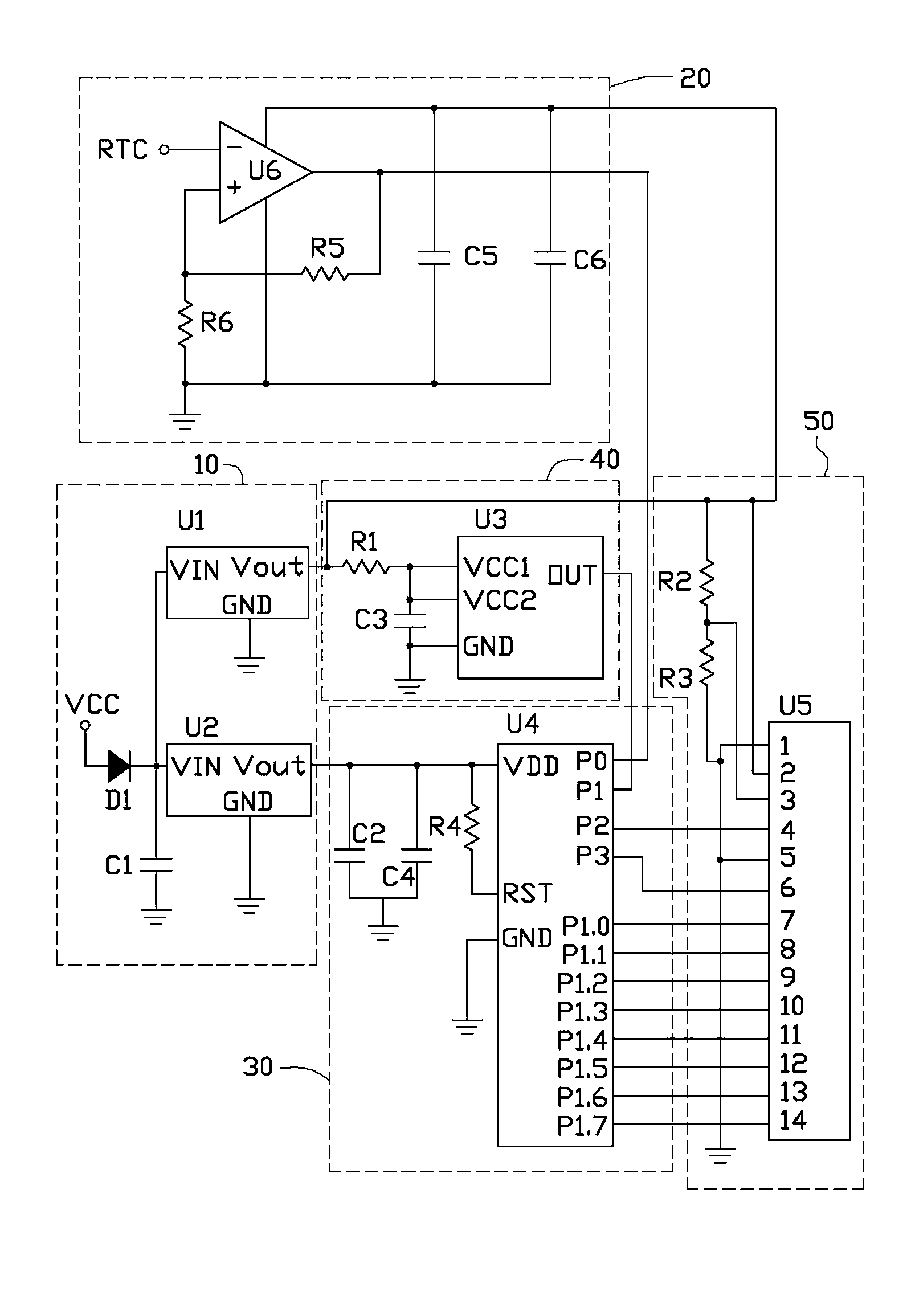
[0015] Please refer to figure 2 , the power circuit 10 includes a diode D1, a capacitor C1 and two power chips U1 and U2. The ground pins GND of the power chips U1 and U2 are both grounded. The input pin VIN of the power chip U1 is connected to the cathode of the diode D1 and grounded through the capacitor C1. The anode of the diode D1 is connected to the power supply VCC. The power chip U1 is used to convert the voltage output by the power supply VCC, and output the converted voltage through the output pin Vout of the powe...


PUM


Abstract

A system for testing a real time clock (RTC) includes a frequency-dividing circuit configured to generate a frequency-dividing clock pulse signal equal to a rated frequency of a clock pulse signal generated by the RTC, and a control circuit including a processing chip. The processing chip includes a timer and a counter. The timer is used to record a test time of the RTC, the counter is used to record a pulse difference between the clock pulse signal and the frequency-dividing clock pulse signal during the test time. If a pulse rate difference between the counter and the timer is greater than a standard clock pulse difference, the RTC is unqualified, and if the pulse rate difference between the counter and the timer is less than the standard clock pulse difference, the RTC is qualified.

Description

technical field [0001] The invention relates to a clock testing circuit. Background technique [0002] The system time of the computer is provided by the pulse signal generated by the clock circuit composed of the crystal oscillator and related components on the main board, wherein the pulse frequency output by the clock circuit is 32.768KHz. Usually, the frequency generated by the crystal oscillator in the clock circuit is affected by the temperature, so a certain time error will be generated more or less, thus affecting the accuracy of the system time. Therefore, it is necessary to test whether the time error of the frequency generated by the crystal oscillator is within a certain range. The general industry requirement is that the deviation between the time generated by the clock circuit and the standard time within 24 hours should be less than 2 seconds. However, if the deviation between the time generated by the clock circuit and the standard time is 2.3 seconds, it i...

Claims


Application Information

Patent Timeline
Patent Type & Authority Applications(China)
IPC IPC(8): G01R31/28
CPCG01R31/31727
Inventor 郭强
Owner HONG FU JIN PRECISION IND (SHENZHEN) CO LTD
Why Eureka
Try Eureka