
Cycloidal pin wheel speed reducer

A pin wheel reducer, cycloid technology, applied in the direction of gear transmission, belt/chain/gear, transmission parts, etc., can solve the problem that the reducer does not directly realize fixed-axis transmission, the radial size of the reducer is large, and the Increase the axial size of the reducer and other issues to achieve the effect of compact structure, improved bearing capacity, and enlarged bearing size

Inactive Publication Date: 2014-01-22
BEIJING RES INST OF PRECISE MECHATRONICS CONTROLS +1
View PDF9 Cites 10 Cited by
  • Summary
  • Abstract
  • Description
  • Claims
  • Application Information

AI Technical Summary

Problems solved by technology

[0003] The general cycloidal pin wheel planetary reducer is mainly composed of input shaft, double eccentric sleeve, arm bearing, cycloidal wheel, pin tooth, column pin, column pin sleeve and output shaft, etc. The eccentric device in the reducer is the weak link , the arm bearing is inside the output mechanism on the cycloid wheel, and the radial size is limited, which limits the cycloid pin wheel planetary transmission to fully exert its carrying capacity, and at the same time, the axial size is relatively large
[0004] The double-crank ring-plate type pin pendulum planetary reducer retains the original cycloid pin wheel planetary reducer with a large number of meshing teeth at the same time, the angle between the total normal force and the total circumferential force is small, and the cycloid wheel and pin wheel teeth are hard tooth surfaces, etc. Essential advan

Method used


Image

  • Cycloidal pin wheel speed reducer
  • Cycloidal pin wheel speed reducer
  • Cycloidal pin wheel speed reducer

Examples


Embodiment Construction

[0023] The present invention will be described in further detail below in conjunction with the accompanying drawings and specific embodiments.

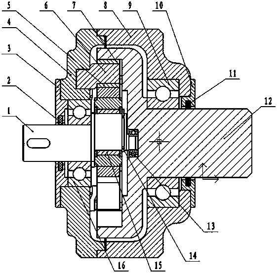
[0024] Such as figure 1 As shown, the input shaft 1 is an eccentric shaft, and a needle roller bearing 15 without an outer ring is installed on the outside of the shaft. One end of the input shaft 1 is provided with a support bearing 13, and the other end is provided with an input end support bearing 16.

[0025] Pin teeth 6 are engaged with the outside of the above-mentioned epicycloid wheel 5 , and pin teeth copper sleeves 7 are installed outside the pin teeth 6 .

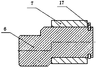
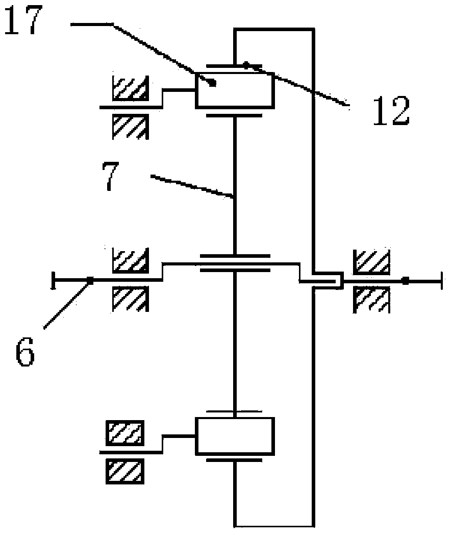
[0026] Such as figure 2 As shown, the pin teeth 6 are eccentric pin teeth, one end of the pin teeth 6 is covered with a pin tooth copper sleeve 7, and the end of the copper sleeve 7 is installed with a retaining ring 17 for the shaft. Corresponding tooth-shaped structures are processed on the inner and outer walls of the pin-toothed copper sleeve 7 , so the inner wal...


PUM


Abstract

The invention belongs to the technical field of spaceflight servo mechanisms and particularly discloses a cycloidal pin wheel speed reducer. The cycloidal pin wheel speed reducer comprises an input support, an output support, an input shaft and an output shaft, wherein the input support and the output support are fixedly connected, wherein the input shaft is an eccentric shaft, a non-outer-ring needle bearing is arranged outside the input shaft, an epicycloidal wheel is arranged outside the needle bearing, needle teeth are arranged outside the epicycloidal wheel in a meshing mode, an output shaft supporting bearing is arranged outside the shaft end of the output shaft, and the output support is located outside the output shaft supporting bearing. A retainer and a connection bolt are structurally omitted, and a W output mechanism is omitted, so that the axial size of the reducer is short, and a structure is more compact. The needle teeth are designed to be of eccentric structures, the epicycloidal wheel is eccentrically arranged relative to a hypocycloid wheel, the needle teeth eccentrically rotate while the positions of the rotary centers are fixed, and the rotary centers of the needle teeth are distributed on a concentric circle coincident with the rotary center of the hypocycloid wheel. The structural form is favorable for increasing the tooth number of the needle teeth meshed with the cycloid gears at the same time, and bearing capacity for transmission is improved.

Description

technical field [0001] The invention belongs to the technical field of aerospace servo mechanisms, and in particular relates to a cycloidal pinwheel reducer. Background technique [0002] Cycloidal pin gear reducer is a kind of planetary transmission reducer with small tooth difference. It has a series of advantages such as compact structure, light weight, large transmission ratio range, high transmission efficiency, stable and reliable transmission, etc. It can replace two-stage, The three-stage ordinary cylindrical gear reducer meets the needs of aerospace light weight, miniaturization and high reliability. [0003] The general cycloidal pin wheel planetary reducer is mainly composed of input shaft, double eccentric sleeve, arm bearing, cycloidal wheel, pin tooth, column pin, column pin sleeve and output shaft, etc. The eccentric device in the reducer is the weak link , The arm bearing is inside the output mechanism of the cycloid wheel, and the radial size is limited, wh...

Claims


Application Information

Patent Timeline
IPC IPC(8): F16H1/32F16H57/023F16H57/029
CPCF16H1/32F16H57/023F16H57/029F16H2001/323
Inventor 侍威王惠娟崔佩娟黄玉平王春明
Owner BEIJING RES INST OF PRECISE MECHATRONICS CONTROLS
Learn More