Low-water-resistance ship with impellers provided with water more fully

A technology with low water resistance and impeller, applied in the direction of ship hull, ship propulsion, ship parts, etc., can solve the problems of limited water supply, affecting ship speed, affecting water discharge speed, etc.

Inactive Publication Date: 2014-01-22
CHONGQING TENGGUAN MACHINERY CO LTD
View PDF7 Cites 0 Cited by
  • Summary
  • Abstract
  • Description
  • Claims
  • Application Information

AI Technical Summary

Problems solved by technology

In order to reduce the contact area and resistance between the ship and the water, the shape of the bottom of the ship is warped forward based on the horizontal plane. When the ship is running, the bottom surface of the front end of the ship is away from the water surface. If it is pumped into the speed-increasing tube, it is easy to have the above-mentioned air intake problem, which will affect the further improvement of the ship's speed
On the other hand, the water inlet diameter at the front end of the speed-increasing pipe is similar to the water outlet diameter at the rear end. When the impeller drains water at high speed, the water supply is limited, which ultimately affects the drainage speed, and the speed-up effect is not ideal.

Method used


Image

  • Low-water-resistance ship with impellers provided with water more fully

Examples


Embodiment Construction

[0019] The present invention will be further described below in conjunction with the accompanying drawings and examples.

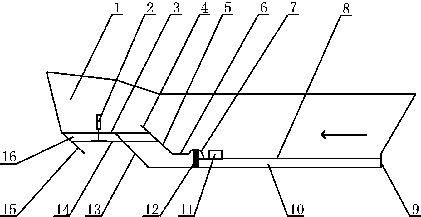
[0020] Such as figure 1 As shown, the present embodiment includes a hull 1 with a power machine 11, and also includes a speed-up compartment surrounded by the bottom of the ship and the speed-up bulkhead 10 located below the bottom of the ship. The speed-up chamber is only open at the front and rear ends. The bilges of the speed-up cabins are at the same level.

[0021] The bottom of the ship is sequentially connected end to end with a horizontal air-blocking section 3, a contraction section 5, a water entry section 6, an arched section 7, and a water outlet section 8, and each section has the same width, which is not less than that of the bottom of the ship. width. The bottom surfaces of the horizontal gas blocking section 3, the contraction section 5, the water entry section 6 and the water exit section 8 are all planes. The front end of the horizont...


PUM


Abstract

The invention discloses a low-water-resistance ship with impellers provided with water more fully. The low-water-resistance ship comprises a ship body and an accelerating cabin located below a ship bottom. A horizontal air-resisting section, a contraction section, a water inlet section, an arching section and a water outlet section which are connected in an end-to-end mode are sequentially arranged on the ship bottom from front to back. An opening in the back end of the accelerating cabin is a water outlet which is located in the tail of the ship body. An opening in the front end of the accelerating cabin is a water inlet, and the upper end of the water inlet in the accelerating cabin wall is located in the middle of the horizontal air-resisting section. The horizontal air-resisting section, the water inlet section and ship bottom face of the water outlet section are parallel to one another. The arching section arches upwards and is internally provided with two impellers which are located at the same level position and are arranged side by side. The two impellers are respectively connected with a motor in a transmission mode. The accelerating cabin sequentially becomes thinner from front to back, the impellers are provided with water more fully, the water flows faster, and the front suction and back pushing effect is more obvious. Due to the fact that the arching section on which the impellers are installed is arranged, the working area of the impellers is far larger than the sectional area of a cavity in the lower portion of the water outlet section. Therefore, the ship has a higher driving speed.

Description

[0001] [0002] This application is a divisional application. The patent number of the original case is: 201110118724.2, the application date: April 29, 2011, and the invention name is: a boat with low water resistance. technical field [0003] The invention relates to a ship, which includes large, medium and small ships, submarines, ships and aircraft carriers. Background technique [0004] The current boats are very slow, and the concept of high horsepower and low speed has been adopted. The ensuing problem is that the speed of the ship cannot be increased simply by increasing the propeller speed. There are two reasons for this phenomenon. One is that the resistance of water is greater, and the deeper the draft, the greater the resistance; the other is air intake, because the ship is driving between water and air, and the natural flow rate of water is at a certain depth. There is a certain limit. When the speed of the propeller exceeds a certain limit, there will be n...

Claims


Application Information

Patent Timeline
Patent Type & Authority Applications(China)
IPC IPC(8): B63B1/36B63H5/04B63H21/17
CPCY02T70/121Y02T70/10
Inventor 车培彩
Owner CHONGQING TENGGUAN MACHINERY CO LTD
Why Eureka
Try Eureka