Wire clamping mechanism for numerical-control wire bending machine
A wire clamping mechanism and wire bending machine technology, which is applied in the field of mechanical processing equipment, can solve problems affecting the quality of bending wires, difficulty in inserting segmented wires, and unreliable clamping and fixing of segmented wires, etc., and achieve the effect of improving feeding accuracy
Inactive Publication Date: 2014-01-22
惠州市嘉兴隆精密机械科技有限公司
View PDF8 Cites 1 Cited by
- Summary
- Abstract
- Description
- Claims
- Application Information
AI Technical Summary
Problems solved by technology
However, in the prior art, there is no wire bending machine that bends wire rods section by section.
The problem that the continuous wire bending machine cannot be directly used to bend the segmented wire is: first, the existing feeding mechanism cannot realize the feeding of the segmented wire; It is difficult to insert into the hole; the third is that when the bent wire is formed, the segmented wire cannot be reliably clamped and fixed, which affects the quality of the bent wire
Method used
View moreImage
Smart ImageViewing Examples

Examples
Embodiment 1
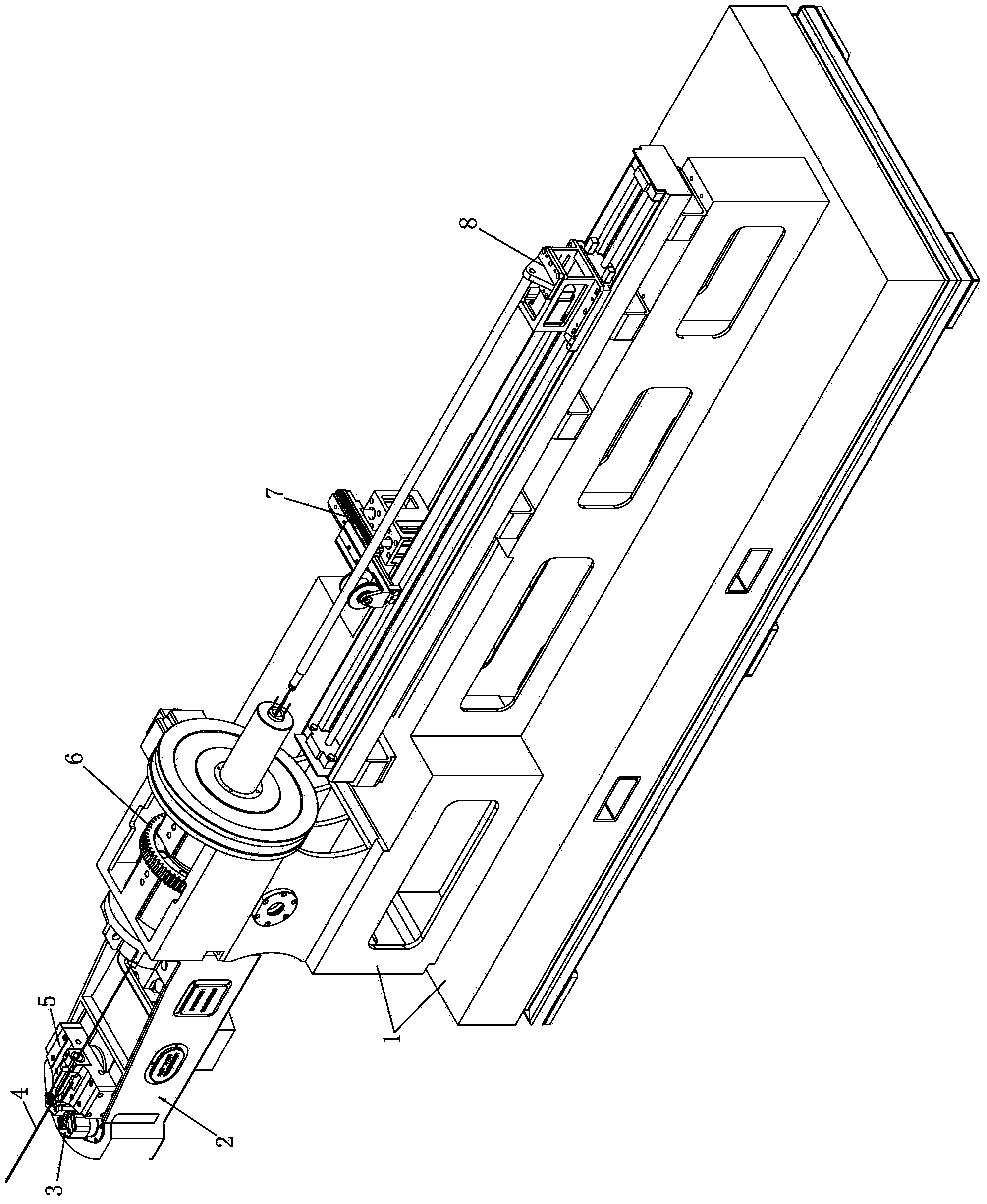
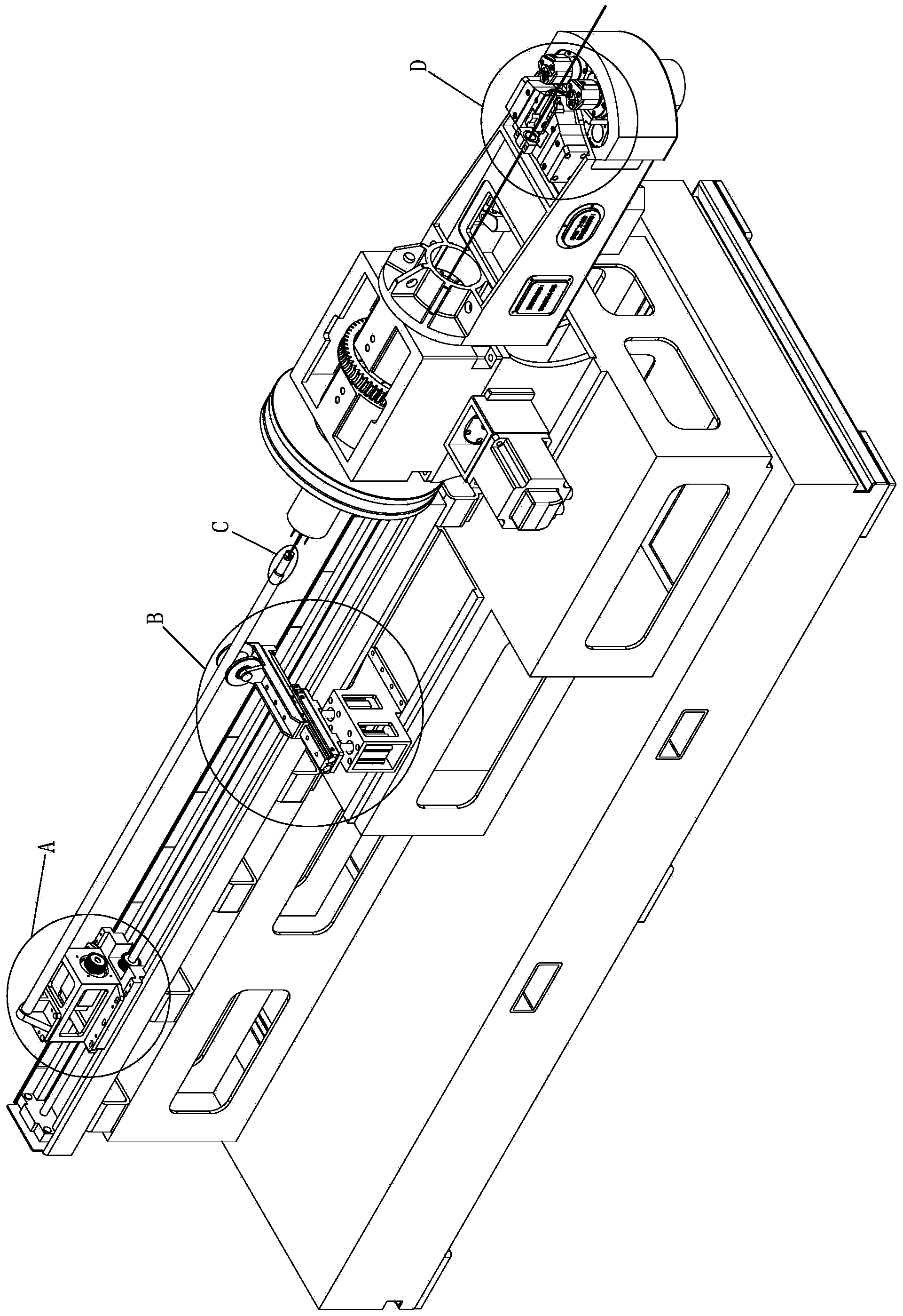
[0015] like figure 1 , figure 2 A numerically controlled wire bending machine shown includes a frame 1, on which a machine head 2, a machine head rotating mechanism 6 and a feeding device are sequentially arranged from front to back, wherein the machine head 2 is provided with a bending die 3 and its Mold rotation mechanism, mold conversion mechanism.
Login to View More PUM
 Abstract
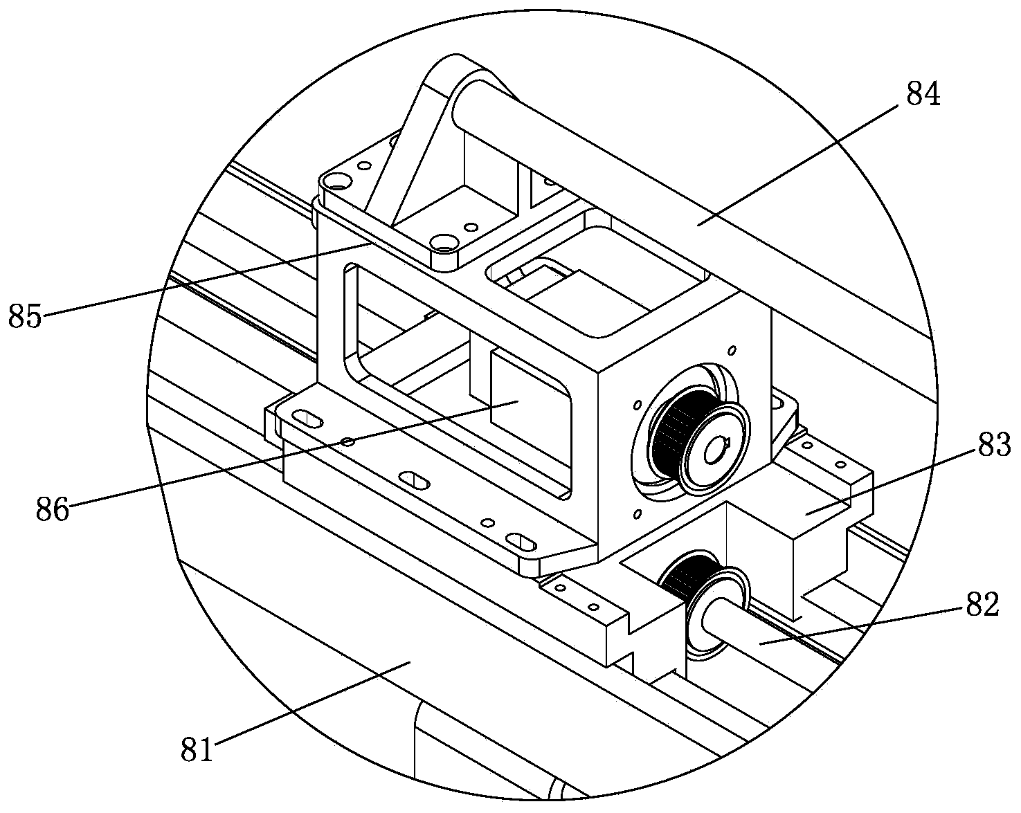
The invention discloses a wire clamping mechanism for a numerical-control wire bending machine. The wire clamping mechanism comprises two wire clamping oil cylinders and two clamping dies. The wire clamping oil cylinders are relatively arranged in a left-and-right mode, and the moving ends of the two wire clamping oil cylinders are relatively ejected out in a left-and-right mode so as to drive the two clamping dies to move to achieve butt clamping. Wire clamping nozzles are formed in the positions, close to the front portions of the wire bending dies, of the two clamping dies, clamping grooves which are matched with wire rods are formed in the wire clamping nozzles, grooves are formed in the positions, behind the wire clamping nozzles, of the two clamping dies and allow the front ends of material feeding rods to be penetrated, guide sleeves which penetrate through the segmented wire rods and the material feeding rods are arranged on the rear sides of the two clamping dies, the guide sleeves are installed on guide sleeve bases, and the guide sleeve bases are fixed on the machine head. According to the technical scheme, the material feeding rods and the wire rods fixedly locked at the front ends of the material feeding rods are adopted to enable feeding of the segmented wire rods and wire bending machining to be implemented, synchronous movement of a motor and a sliding block is adopted, ancillary shoring is carried out on a guide mechanism, the moving feeding precision is improved, the structure is simple and reasonable, and the manufacturing cost is low.
Description
technical field [0001] The invention belongs to the field of mechanical processing equipment, in particular to a wire clamping mechanism for a numerically controlled wire bending machine. Background technique [0002] The patent documents whose publication numbers are CN201231294Y and CN101716636A respectively disclose two kinds of numerically controlled wire bending machines. Their structures are similar, and they are all used for bending wire forming of continuous wires (such as steel wire coils), including a frame on which there are Straightening mechanism, wire feeding mechanism, machine head rotation mechanism, machine head, cutting mechanism, mold, mold rotation mechanism, mold conversion mechanism and control unit. However, there is no wire bending machine that bends wire rods section by section in the prior art. The problem that the continuous wire bending machine cannot be directly used to bend the segmented wire is: first, the existing feeding mechanism cannot rea...
Claims
Login to View More Application Information
Patent Timeline
 Patent Type & Authority Applications(China)
IPC IPC(8): B21F1/00B21F23/00
Inventor 吴敏高尔荣
Owner 惠州市嘉兴隆精密机械科技有限公司
Features
- Generate Ideas
- Intellectual Property
- Life Sciences
- Materials
- Tech Scout
- Unparalleled Data Quality
- Higher Quality Content
- 60% Fewer Hallucinations
Learn More Browse by: Latest US Patents, China's latest patents, Technical Efficacy Thesaurus, Application Domain, Technology Topic, Popular Technical Reports.
© 2025 PatSnap. All rights reserved.Legal|Privacy policy|Modern Slavery Act Transparency Statement|Sitemap|About US| Contact US: help@patsnap.com