
Intelligent reduction system for long bone fracture

A long bone and control system technology, applied in medical science, surgical manipulators, surgery, etc., can solve problems such as long traction time, reduced local resistance of fractures, and damage to blood supply, so as to avoid trauma and pain, and achieve accurate fracture reduction. smart effect

Active Publication Date: 2014-01-15
FOURTH MILITARY MEDICAL UNIVERSITY
View PDF5 Cites 9 Cited by
  • Summary
  • Abstract
  • Description
  • Claims
  • Application Information

AI Technical Summary

Problems solved by technology

1. Insufficient manual reduction: 1) Under fluoroscopy, doctors and patients will be exposed to a large amount of X-rays; 2) If it is performed under the guidance of X-ray films, it will not be able to understand and guide the reset in time, and it is necessary to take another film after fixation. Knowing the reduction situation often leads to unsatisfactory reduction of the fracture, and often requires re-reduction, or even repeated resets many times, which increases the trauma and pain of the patient; Frequent loss of reset
2. Insufficient traction reduction: 1) The traction time is long, and it usually takes one to several months; 2) The patient needs to stay in bed during the traction, which severely limits the patient's activities and functional exercises; To avoid problems such as insufficient traction or excessive traction; 4) The effect of traction reduction and fixation is poor
3. Insufficient surgical reduction: 1) Increase the trauma and pain of the patient; 2) Damage to the soft tissue and periosteum around the fracture will further damage the local blood supply and affect fracture healing; 3) Reduce the local resistance of the fracture and increase Risk of infection; 4) Most of the internal fixation needs to be re-operated to remove

Method used


Image

  • Intelligent reduction system for long bone fracture
  • Intelligent reduction system for long bone fracture

Examples


Embodiment Construction

[0011] The present invention will be described in detail below in conjunction with the accompanying drawings.

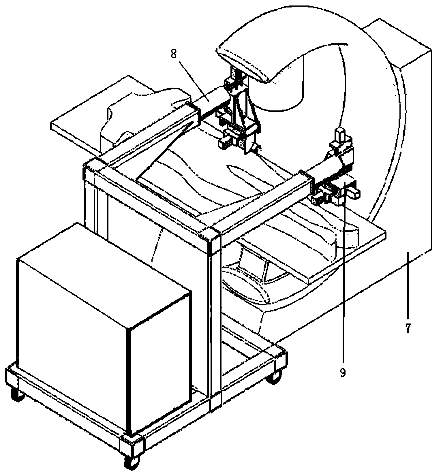
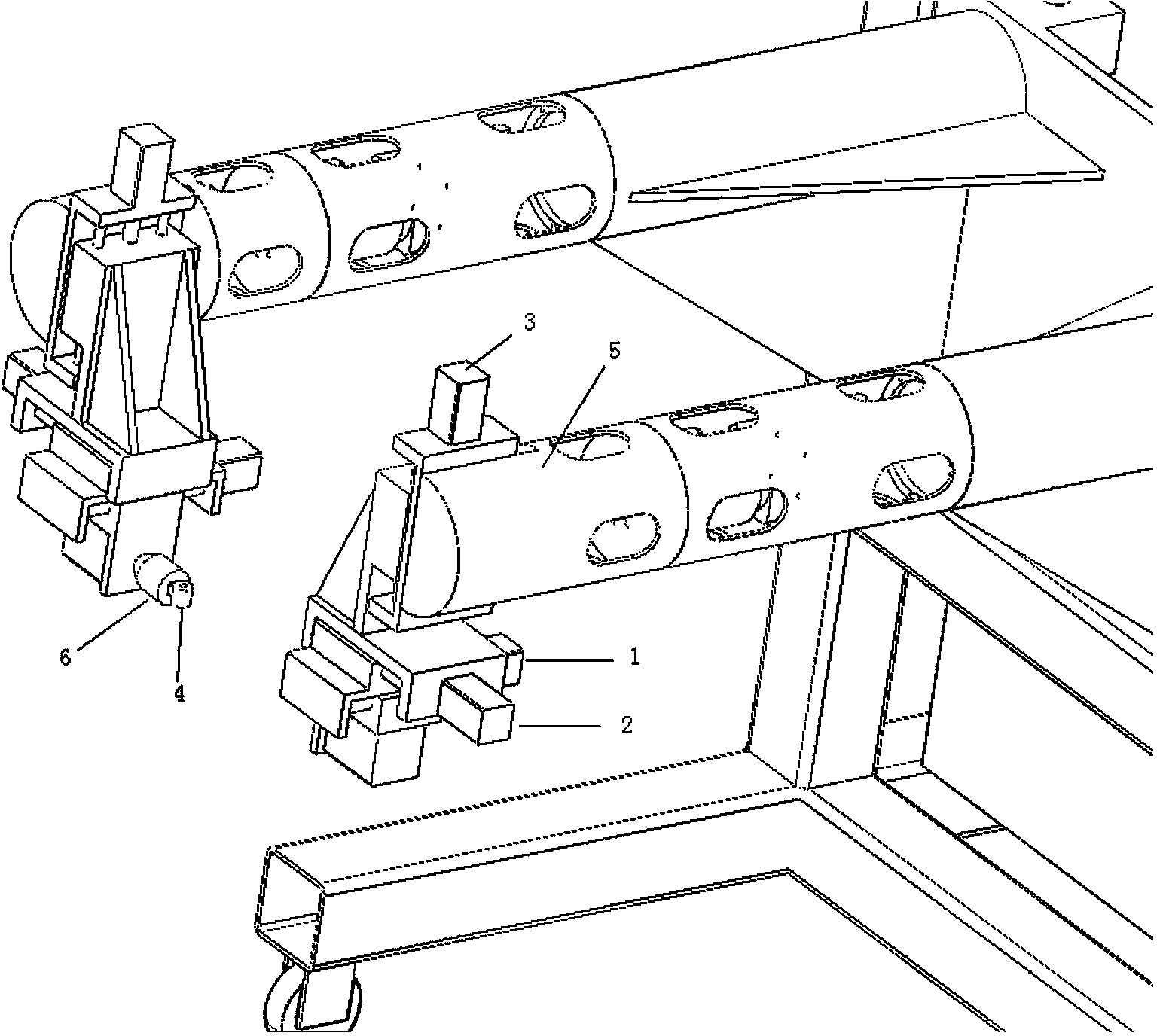
[0012] see figure 1 and figure 2 , the present invention includes a fluoroscopy system 7, the image transmission device of the computer control system is used to receive the image of the fluoroscopy system 7, and the instruction of the computer control system is used to control the input device to control the reset mechanical arm 8 that makes corresponding actions, and the reset mechanical arm 8 There is a five-axis manipulator 9 driven by the reset manipulator 8 to move the fracture site, wherein the five-axis manipulator 9 includes a lateral displacement track for positive and negative two-way translational movements on the three coordinate axes of X-axis, Y-axis and Z-axis 1. Longitudinal displacement track 2 and vertical displacement track 3, as well as horizontal plane rotation axis 4, sagittal plane rotation axis 5 and transverse plane rotation axis 6 for pos...


PUM


Abstract

The invention relates to an intelligent reduction system for a long bone fracture. In order to avoid a long bone fracture open reduction fixing operation and achieve precise, minimally invasive and intelligent fracture reduction fixing and even if remote treatment, according to the technical scheme, the intelligent reduction system comprises a perspective system, a computer control system and a reduction mechanical arm, wherein the computer control system is used for receiving images of the perspective system, and the reduction mechanical arm is controlled by the computer control system to perform corresponding actions. A five-shaft manipulator is arranged on the reduction mechanical arm, is driven by the reduction mechanical arm and enables the fracture portion to perform positive and negative bi-direction translation, tilt and rotation in the X coordinate axis, the Y coordinate axis and the Z coordinate axis. By the adoption of the technical scheme, a doctor will not be subjected to a great deal of radioactive irradiation in the perspective reduction process, increased wounds and pains, caused by long bone fracture open reduction, of a patient are avoided, and the purpose of precise, intelligent and minimally invasive closed reduction for the fracture is achieved.

Description

technical field [0001] The invention relates to a fracture reduction system, in particular to an intelligent reduction system for long bone fractures. Background technique [0002] The essence of fracture treatment is to reduce and fix the fracture. At present, traditional reduction methods are roughly divided into three types, including manual reduction, traction reduction, and open (surgical) reduction. But all have respective deficiencies. 1. Insufficient manual reduction: 1) Under fluoroscopy, doctors and patients will be exposed to a large amount of X-rays; 2) If it is performed under the guidance of X-ray films, it will not be able to understand and guide the reset in time, and it is necessary to take another film after fixation. Knowing the reduction situation often leads to unsatisfactory reduction of the fracture, and often requires re-reduction, or even repeated resets many times, which increases the trauma and pain of the patient; Lost resets often occur. 2. In...

Claims


Application Information

Patent Timeline
IPC IPC(8): A61B17/60A61B6/00
CPCA61B6/00A61B17/60A61B34/70
Inventor 袁志焦腾吴岩裴国献刘建毕龙杨鹏李岩隋天琪
Owner FOURTH MILITARY MEDICAL UNIVERSITY
Learn More