A High-Precision Dual-Frequency Simultaneous Measurement of Laser Heterodyne Interferometry Phase Vibration Optical Path

A technology for measuring laser and heterodyne interference. It is used in measuring devices, measuring ultrasonic/sonic/infrasonic waves, instruments, etc. It can solve the problem of low accuracy and achieve the effects of high phase measurement accuracy, high precision and simple signal processing process.

Inactive Publication Date: 2016-04-13
BEIJING INSTITUTE OF TECHNOLOGYGY
View PDF6 Cites 0 Cited by
  • Summary
  • Abstract
  • Description
  • Claims
  • Application Information

AI Technical Summary

Problems solved by technology

[0006] The purpose of the present invention is to overcome the deficiencies of the prior art and provide a high-precision dual-frequency simultaneous measurement laser heterodyne interference phase vibration measurement optical path, which adopts the heterodyne interference optical path, has good stability, and both frequency components participate in the measurement , the frequency difference has changed by 2Δf, which is equivalent to doubling the measurement accuracy, and the phase measurement method is used to demodulate the frequency difference change signal, which solves the problem that the commonly used heterodyne laser vibrometer is not accurate when measuring low-frequency vibration objects. And phase measurement can further improve the accuracy of laser vibration measurement

Method used


Image

  • A High-Precision Dual-Frequency Simultaneous Measurement of Laser Heterodyne Interferometry Phase Vibration Optical Path

Examples


Embodiment Construction

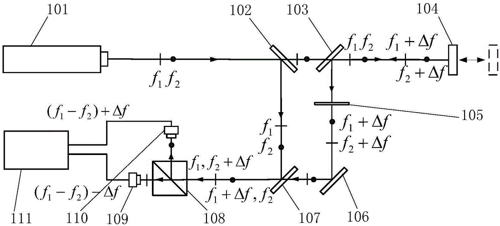
[0014] Please refer to the accompanying drawings, the dual-frequency laser source (101) adopts a transverse Zeeman dual-frequency laser with a frequency difference of 3MHz, and sends out a pair of linearly polarized light with a wavelength of 633nm orthogonal to each other, and its frequency components parallel and perpendicular to the paper surface They are f1 and f2 respectively, and the frequency difference is 5MHz. The first half-mirror (102) is k9 optical glass coated with a semi-permeable film, and the light beam is divided into two parts after passing through (102), both of which contain f1 and f2 frequency components. Wherein the reflected light is incident to the third half-mirror (107), (107) is the same product as (102), and the transmitted light is incident to the sample to be measured ( 104) Surface, (103) is also the same product as (102), (104) adopts a thin steel sheet driven by piezoelectric ceramics, and the vibration frequency is set to 500KHz. Due to the D...


PUM


Abstract

The invention relates to the field of laser interference measurement, in particular to a novel high-precision double-frequency simultaneous measurement laser heterodyne interference phase vibration measuring light path, which comprises a double-frequency laser source, a first semitransparent semi-reflection mirror, a second semitransparent semi-reflection mirror, a third semitransparent semi-reflection mirror, a sample, a half wave plate, a total reflection mirror, a polarization spectroscope, a first detector, a second detector and a phase measuring instrument. The laser source sends out mutually orthogonal linearly polarized light with the frequency components being f1 and f2, light beams are divided into two beams after passing through the first semitransparent semi-reflection mirror, transmission light sequentially passes through the second semitransparent semi-reflection mirror, the sample, the half wave plate with the fast axis angle being 45 degrees and the total reflection mirror, and is subjected to light combination with reflected light at the third semitransparent semi-reflection mirror part, then, the combined light is incident to the polarization spectroscope and is then divided into two beams of light respectively containing parallel and vertical components, the light containing the horizontal component is transmitted and is then received by the first detector to form a first measuring signal, the light containing the vertical component is reflected and is then received by the second detector to form a second measuring signal, the frequency difference 2delta f of the first measuring signal and the second measuring signal is caused by the sample vibration, and in addition, corresponding phase differences are measured by the phase measuring instrument.

Description

technical field [0001] The invention relates to the field of laser interferometry, in particular to a heterodyne laser vibrometer optical path for measuring target motion information using the Doppler principle. In particular, it relates to a high-precision dual-frequency simultaneous measurement laser heterodyne interference phase vibration measurement optical path. Background technique [0002] Vibration measurement is very important in the field of engineering because it can reflect the dynamic characteristics of objects, especially high-speed moving objects. Since 1960, laser Doppler technology has attracted much attention due to its high spatial and temporal resolution, non-contact and disturbance of the measured object in measurement. Since the first paper on laser Doppler velocimetry was published in 1964, the technology has immediately attracted the attention of all parties and a large number of theoretical and experimental studies have been carried out, and remarka...

Claims


Application Information

Patent Timeline
Patent Type & Authority Patents(China)
IPC IPC(8): G01H9/00
Inventor 陈强华刘景海何永熹罗会甫蒋弘吴健王锋
Owner BEIJING INSTITUTE OF TECHNOLOGYGY
Why Eureka
Try Eureka