
Solidification forming device suitable for manufacturing aramid III fibers through dry jetting and wet spinning method

A technology of coagulation forming and wet spinning, which is applied to coagulation forming devices and spinning equipment for manufacturing aramid III fibers, can solve problems such as reasonable control, fast coagulation liquid flow rate, and fiber coagulation and forming defects, so as to reduce motion resistance, The effect of ensuring sufficient solidification and reducing the generation of fuzz

Active Publication Date: 2014-01-08
CHINA BLUESTAR CHENGRAND CO LTD
View PDF9 Cites 5 Cited by
  • Summary
  • Abstract
  • Description
  • Claims
  • Application Information

AI Technical Summary

Problems solved by technology

[0004] The present invention aims to overcome the technical problem that the flow rate of coagulation liquid caused by the existing dry spray-wet spinning coagulation forming device is too fast to be reasonably controlled, thereby providing a method suitable for dry spray-wet spinning method to manufacture aramid III fiber solidification forming device
The invention solves the coagulation and forming defects of the fibers produced by using the low-solid-content aramid III polymerization solution as a raw material by dry spraying and wet spinning, and makes up for the shortcomings of the existing coagulation and forming devices

Method used


Image

  • Solidification forming device suitable for manufacturing aramid III fibers through dry jetting and wet spinning method
  • Solidification forming device suitable for manufacturing aramid III fibers through dry jetting and wet spinning method
  • Solidification forming device suitable for manufacturing aramid III fibers through dry jetting and wet spinning method

Examples


Embodiment 1

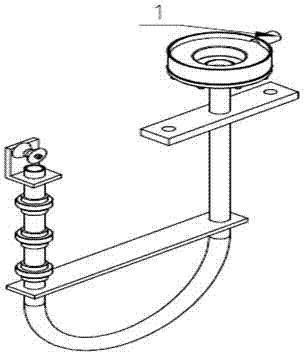
[0029] A coagulation and forming device suitable for producing aramid fiber III by dry spraying-wet spinning method, including two parts: a coagulation plate and a U-shaped coagulation tube. 4. The coagulation plate cover 2 and the overflow pipe 1 are composed. The U-shaped coagulation tube is mainly composed of a U-shaped tube 8, a regulating tube 9, and a wire outlet tube 10. One end of the U-shaped tube 8 is connected with the coagulation plate, and the other end is connected with the coagulation plate. The regulating pipe 10 is flexibly connected.

[0030] The coagulation plate is provided with a liquid inlet 6, a liquid outlet 7, and an overflow pipe 1. The U-shaped coagulation tube has a liquid inlet and a liquid outlet, and the liquid inlet of the U-shaped coagulation tube and the liquid outlet of the coagulation plate 7 connections, and a guide wheel 11 is provided at the liquid outlet of the U-shaped coagulation tube.

[0031] The liquid outlet of the U-shaped coagul...

Embodiment 2

[0038] A coagulation and forming device suitable for producing aramid fiber III by dry spraying-wet spinning method, including two parts: a coagulation plate and a U-shaped coagulation tube. 4. The coagulation plate cover 2 and the overflow pipe 1 are composed. The U-shaped coagulation tube is mainly composed of a U-shaped tube 8, a regulating tube 9, and a wire outlet tube 10. One end of the U-shaped tube 8 is connected with the coagulation plate, and the other end is connected with the coagulation plate. The regulating pipe 10 is flexibly connected.

[0039] The coagulation plate is provided with a liquid inlet 6, a liquid outlet 7, and an overflow pipe 1. The U-shaped coagulation tube has a liquid inlet and a liquid outlet, and the liquid inlet of the U-shaped coagulation tube and the liquid outlet of the coagulation plate 7 connections, and a guide wheel 11 is provided at the liquid outlet of the U-shaped coagulation tube.

[0040] The liquid outlet of the U-shaped coagul...

Embodiment 3

[0047] A coagulation and forming device suitable for producing aramid fiber III by dry spraying-wet spinning method, including two parts: a coagulation plate and a U-shaped coagulation tube. 4. The coagulation plate cover 2 and the overflow pipe 1 are composed. The U-shaped coagulation tube is mainly composed of a U-shaped tube 8, a regulating tube 9, and a wire outlet tube 10. One end of the U-shaped tube 8 is connected with the coagulation plate, and the other end is connected with the coagulation plate. The regulating pipe 10 is flexibly connected.

[0048] The coagulation plate is provided with a liquid inlet 6, a liquid outlet 7, and an overflow pipe 1. The U-shaped coagulation tube has a liquid inlet and a liquid outlet, and the liquid inlet of the U-shaped coagulation tube and the liquid outlet of the coagulation plate 7 connections, and a guide wheel 11 is provided at the liquid outlet of the U-shaped coagulation tube.

[0049] The liquid outlet of the U-shaped coagul...


PUM

PropertyMeasurementUnit
diameteraaaaaaaaaa
heightaaaaaaaaaa
diameteraaaaaaaaaa

Abstract

The invention discloses a solidification forming device suitable for manufacturing aramid III fibers through a dry jetting and wet spinning method. The solidification forming device comprises a solidification plate and a U-shaped solidification pipe, wherein the solidification plate is mainly composed of a solidification plate base, a sealing gasket, a solidification liquid distribution net, a solidification plate cover and an overflow tube, the U-shaped solidification pipe is mainly composed of a U-shaped pipe, an adjusting pipe and a fiber outlet pipe, one end of the U-shaped pipe is connected with the solidification plate, and the other end of the U-shaped pipe is movably connected with the adjusting pipe. The height difference between a liquid inlet of the U-shaped solidification pipe and a liquid outlet of the U-shaped solidification pipe can be adjusted according to the requirement for the spinning speed. Rapid and uniform solidification of aramid III nascent fibers can be achieved through the solidification forming device, the spinning speed of the aramid III fibers can be remarkably improved, production efficiency is improved, meanwhile, the manufactured fibers are good in quality, small in the number of burrs and neater in appearance, and due to the fact that the device is small in size and compact in structure, modularized manufacturing and replacement can further be achieved.

Description

technical field [0001] The invention relates to spinning equipment for producing aramid III fibers, in particular to a coagulation forming device in a dry jet-wet spinning method, and belongs to the technical field of chemical synthetic fiber equipment. Background technique [0002] Aramid Ⅲ belongs to domestic high-performance organic fibers with high strength, high modulus, and high temperature resistance. It has now become a reinforcing fiber for the preparation of advanced composite materials for aerospace. At present, the industrial production of aramid fiber III at home and abroad is manufactured by wet spinning technology. The coagulation bath is the main equipment in the wet spinning process. In the coagulation technology of aramid III fiber wet spinning, the coagulation bath is usually a horizontal coagulation tank. The coagulation bath enters the bath from the end (front) where the spinneret is installed, and flows to the other end (rear) of the bath in parallel ...

Claims


Application Information

Patent Timeline
Patent Type & Authority Applications(China)
IPC IPC(8): D01D13/02D01D5/06
Inventor 彭涛王凤德刘克杰章胜宗杨文良杨杰
Owner CHINA BLUESTAR CHENGRAND CO LTD
Learn More