
Cooling method and structure of closed type cooling system

A cooling system and cooling method technology, applied in cooling/ventilation/heating renovation, heat exchange equipment, lighting and heating equipment, etc., can solve the problems of unstable output temperature, large setting capacity, insufficient cooler capacity, etc. The effect of stable output temperature, simplified system analysis, and improved system structure

Active Publication Date: 2014-01-01
DONGFANG ELECTRIC AUTOMATIC CONTROL ENG CO LTD +1
View PDF3 Cites 12 Cited by
  • Summary
  • Abstract
  • Description
  • Claims
  • Application Information

AI Technical Summary

Problems solved by technology

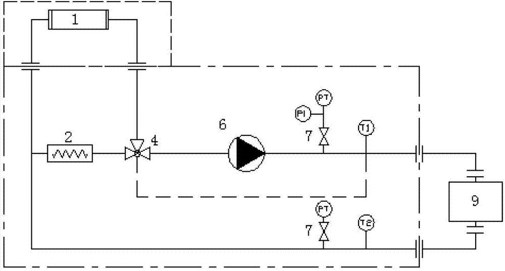
[0003] 1. The heat balance equation between the heat output of the object to be cooled and the cooling system has not been established, and the opening of the control valve is only related to the temperature difference (T set -T1) is related, the start and stop of the fan is only related to the given temperature T set There is a relationship, but the temperature and temperature difference cannot represent the calorific value of the cooled system. The calorific value is generally a multivariate nonlinear equation (Formula 2), which cannot be solved accurately by arithmetic methods, so the cooling system cannot understand the overall system performance. The actual state, so that precise design cannot be realized, and intelligent control cannot be realized
[0004] 2. There is no strict derivation of the functional relationship of the cooling system, and the functional relationship between the opening of the control valve, the cooling capacity output of the cooling system and the calorific value of the object to be cooled has not been established, so it is impossible to use theoretical analysis to determine the real-time efficiency of the cooling system, that is, Unable to design an energy-efficient cooling system
[0005] 3. The output temperature of the cooling system is not constant
Since the existing cooling system does not deduce the functional relationship between the heat output of the cooling object and the output of the cooling system, it is impossible to accurately control the output of its own cooling capacity according to the real-time state of the cooled object, so the output temperature of the cooler is generally not constant, which affects the cooling. System works reliably
[0006] 4. Early warning cannot be given when the capacity of the cooler is insufficient. Due to the disconnection between the heat output of the cooling object of the existing cooling system and the output of the cooling capacity of the cooling system, when the cooling capacity of the system is insufficient, only an alarm will be issued when the system temperature is too high, and early warning cannot be realized.
[0007] 5. The contradiction between variable cooling object calorific value (load) and constant system cooling capacity is not resolved
Since the controlled variable temperature or temperature difference is not a necessary and sufficient condition for the heat generation of the system, the heat generation of the system is also related to factors such as time, regardless of the load of the cooling object, it will only be reflected in the temperature difference. There is no difference in the temperature difference under load, so it is impossible to realize the intelligent control of the cooling system, and it is impossible to design a cooling device with an early warning function, let alone an energy-saving cooling device
[0008] To sum up, almost all existing closed cooling devices have shortcomings such as unstable output temperature, unstable cooling effect, large setting capacity, large load impact, no early warning when the cooler capacity is insufficient, and insufficient energy saving. Affect the reliable operation of the system

Method used

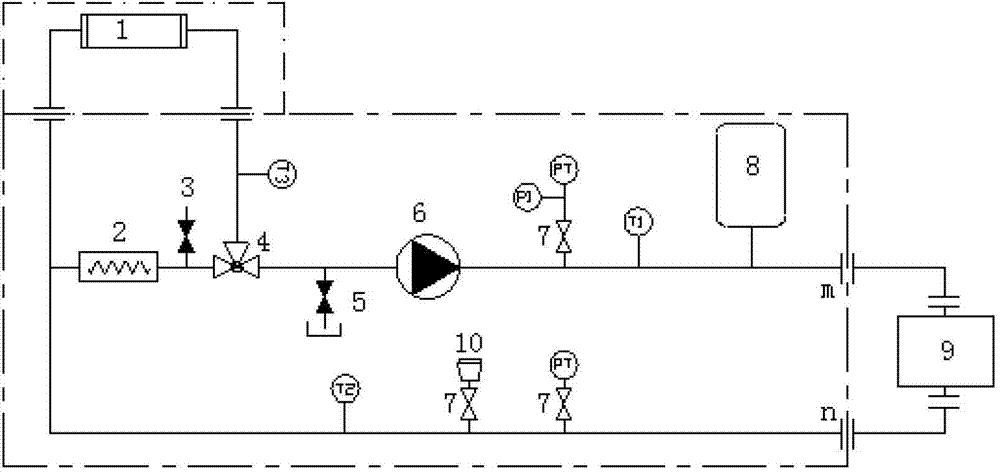
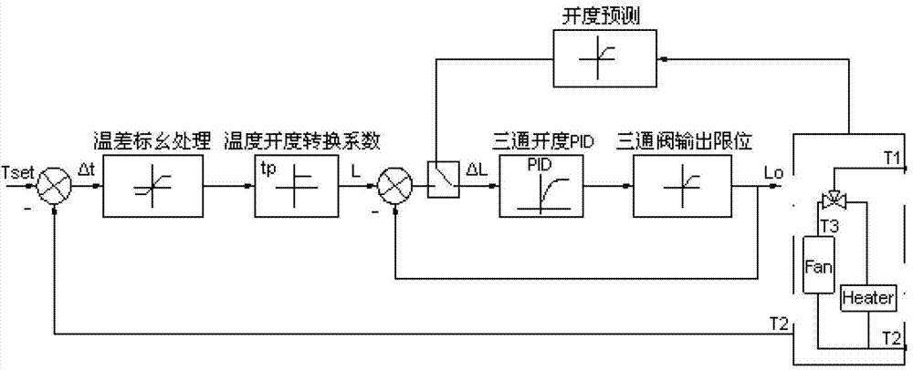

Image

  • Cooling method and structure of closed type cooling system
  • Cooling method and structure of closed type cooling system
  • Cooling method and structure of closed type cooling system

Examples


Embodiment Construction

[0044] like figure 2 , 3 As shown, the closed cooling system of the present invention includes an air-water heat exchanger 1, a heater 2, an exhaust valve 3, a three-way valve 4, a sewage outlet 5, a circulating pump 6, an instrument shut-off valve 7, and a pressure regulator 8. Cool the object 9 and the measuring point joint 10. The cooling object 9 may be any object cooled by water, such as a fan converter and the like. The liquid circulated after the heat exchange of the cooling object 9 is pumped into the air-water heat exchanger 1 and the heater 2 through the circulation pump 6, and then merged through the three-way valve 4 and the flow ratio is controlled to prepare cooling liquid and supply it to the cooling object 9.

[0045] The present invention is a kind of cooling method of closed cooling system, and its concrete steps are:

[0046] (1) According to the calorific value of the cooling object 9, determine the fan that needs to be started in the air-water heat exc...


PUM


Abstract

The invention provides a cooling method of a closed type cooling system. The cooling method specifically includes the steps that firstly, fans needing to be started in an air-water heat exchanger are determined according to the heating amount of a cooled object, and the fan is started; secondly, whether the cooling capacity is sufficient or not is predicted according to the heat balance equation of cooling liquid, when the cooling capacity is insufficient, a standby fan is started by the air-water heat exchanger, and if all the fans are started, alarming is performed by the closed type cooling system; the open value of a tee valve is calculated when the closed type cooling system is dynamically stable according to the function relation between the heating amount of the cooled object and the opening degree of the tee valve, and the practical opening size of the tee valve is kept in the open value. The air-water heat exchanger is composed of three fans which are different in capacity, and seven load sections are combined by the arrangement of the three fans so as to adapt to different demands of the closed type cooling system. The cooling method of the closed type cooling system improves the structure of the system, output temperature is constant, intelligence control is achieved, the early warning function is achieved, and the cooling method of the closed type cooling system is capable of saving energy, friendly to the environment, safe and practical.

Description

technical field [0001] The invention relates to a cooling device, in particular to a cooling method and structure of a closed cooling system. Background technique [0002] The existing closed cooling device generally adopts the control method of "temperature setting + closed-loop feedback", such as figure 1 shown. This control method uses temperature feedback to calculate a given temperature T set The temperature difference from the actual temperature T1 (T set -T1), and then adjust the opening of the control valve (three-way valve) according to the temperature difference to realize the control of the flow through the air-water heat exchanger, thereby realizing the control of the outlet temperature of the cooler. The characteristics of its technology are: the opening of the control valve is only related to the temperature difference (T set -T1) is related, the start and stop of the cooling fan is only related to the given temperature T set There is a relationship, the c...

Claims


Application Information

Patent Timeline
IPC IPC(8): H05K7/20F28F27/00
Inventor 赵军科曹维福王丽娟
Owner DONGFANG ELECTRIC AUTOMATIC CONTROL ENG CO LTD
Learn More