Optical fiber patch cord for high-power laser transmission

A fiber optic jumper and high-power technology, which is applied in the field of SMA connector fiber jumpers, can solve the problems of poor heat dissipation of glue, burning out optical fibers, and difficult processing, and achieve the effects of reducing processing requirements, improving reliability, and reducing costs

Active Publication Date: 2014-01-01
无锡锐科光纤激光技术有限责任公司
View PDF13 Cites 5 Cited by
  • Summary
  • Abstract
  • Description
  • Claims
  • Application Information

AI Technical Summary

Problems solved by technology

The coaxiality of the ferrule, ferrule sleeve, nut and other components of the traditional optical fiber jumper must reach a very high precision to meet the replaceable requirements, and the processing is difficult, requiring ultra-high precision molding or machining processes production, higher cost
Secondly, traditional optical fiber jumpers are used in optical fiber communication to transmit low-power light. Generally, glue is used to fix the optical fiber. The end faces of the optical fiber and the ferrule are flush. After high-power transmission, the glue has poor heat dissipation. Part of the light energy leaked from the fiber head cannot be dissipated, causing the fiber to be burned out. It is used for high-power transmission with low reliability and short life.
On the other hand, tens or even hundreds of watts of light emitted by high-power lasers are completely concentrated on the optical fiber of about a few hundred microns, and the energy is highly concentrated. Any tiny dust or dirt on the end face of the optical fiber will burn the optical fiber

Method used


Image

  • Optical fiber patch cord for high-power laser transmission
  • Optical fiber patch cord for high-power laser transmission

Examples


Embodiment Construction

[0019] The present invention will be further described in conjunction with the accompanying drawings.

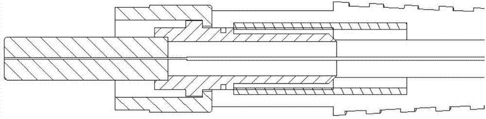
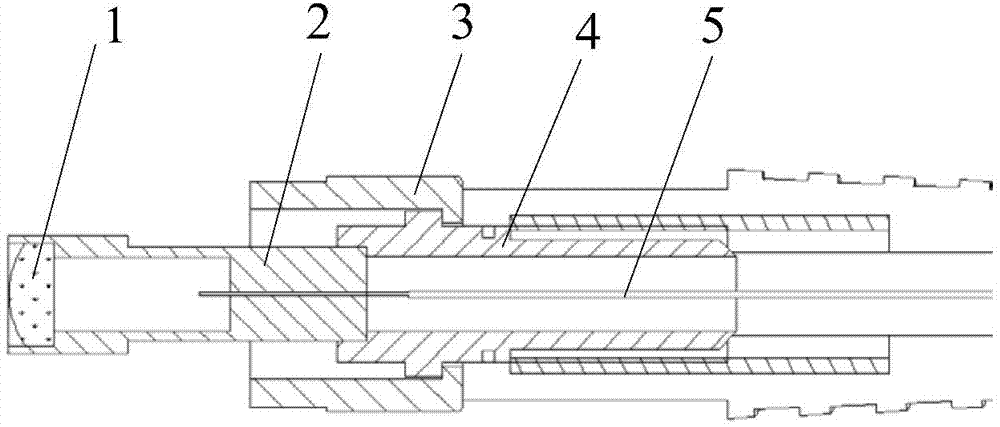
[0020] Such as figure 2 As shown, the present invention includes a collimating lens 1, a ferrule 2, a ferrule sleeve 4, a nut 3, and an optical fiber 5. One end of the ferrule 2 is fixed on the ferrule sleeve 4, and the center of the end of the ferrule 2 is provided with The hole with the same diameter as the optical fiber is used to fix the optical fiber 5; the ferrule sleeve 4 connects the ferrule 2 and the nut 3 together, and the optical fiber 5 passes through the ferrule sleeve 4 and is fixed in the hole of the ferrule 2; The straight lens 1 is fixed at the other end of the ferrule 2 , and the focal point of the collimator lens 1 is at the center of the end face of the optical fiber 5 . The optical fiber 5 is used to receive the light focused by the collimating lens 1 and transmit it. The collimating lens is a lens with a flat surface on one side and an aspheric surfa...


PUM


Abstract

The invention relates to an optical fiber patch cord for high-power laser transmission. The optical fiber patch cord for high-power laser transmission comprises a collimating lens, an insertion core, an insertion core sleeve, a nut and an optical fiber. The optical fiber patch cord for high-power laser transmission is characterized in that one end of the insertion core is fixed to the insertion core sleeve, a hole with the same diameter as the optical fiber is formed in the center of the end, fixed to the insertion core sleeve, of the insertion core, the insertion core and the nut are connected together through the insertion core sleeve, the optical fiber penetrates through the insertion core sleeve and is fixed in the hole of the insertion hole, the collimating lens is fixed to the other end of the insertion core, and the focus of the collimating lens is located at the center of the end face of the optical fiber. The optical fiber patch cord for high-power laser transmission is mainly applied to a transmission system for high-power light. Compared with a traditional optical fiber patch cord, the optical fiber patch cord for high-power laser transmission has the advantages of being good in repeatability, high in reliability, low in environmental influence, long in service life and the like.

Description

technical field [0001] The invention relates to a novel optical fiber jumper for high-power laser transmission. The optical fiber jumper is an SMA connector optical fiber jumper with a collimating lens, and has the advantages of good repeatability, high reliability, and low processing requirements. Background technique [0002] Optical fiber jumper was originally used in optical communication, and it is an indispensable repetitive general-purpose passive device in optical fiber communication system, which is used to realize fast and reliable communication connection between optical fiber and equipment, optical fiber and optical fiber, optical fiber and instrument. It is the fastest growing, most used and most widely used device among passive devices. It is widely used because of its pluggable and easy-to-replace advantages. The optical fiber jumper with SMA connector is fastened by thread, and can be replaced after the optical fiber is broken. [0003] With the development...

Claims


Application Information

Patent Timeline
IPC IPC(8): G02B6/42
Inventor 卢昆忠王文娟胡慧璇费华
Owner 无锡锐科光纤激光技术有限责任公司
Why Eureka
Try Eureka