
2*2 mechanical optical switch

An optical switch and mechanical technology, applied in the coupling of optical waveguides, etc., can solve the problems of low reliability and high production cost, achieve good stability and durability, reduce requirements, and reduce dimensionality.

Active Publication Date: 2014-01-01
广西安捷讯电子科技有限公司
View PDF6 Cites 5 Cited by
  • Summary
  • Abstract
  • Description
  • Claims
  • Application Information

AI Technical Summary

Problems solved by technology

[0006] The technical problem to be solved by the present invention is to solve the problems of low reliability and high production cost of the 2×2 mechanical optical switch in the prior art

Method used


Image

  • 2*2 mechanical optical switch
  • 2*2 mechanical optical switch
  • 2*2 mechanical optical switch

Examples


Embodiment Construction

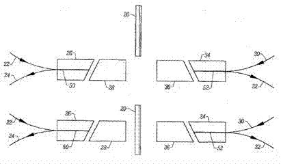
[0022] Such as figure 2 , image 3 Shown: 2×2 mechanical optical switch,

[0023] 1) Including the first optical fiber group and the second optical fiber group, the first optical fiber group gathers the first optical fiber 1, the second optical fiber 2, the fifth optical fiber 5 and the sixth optical fiber 6 together in the axial direction through the capillary glass tube 9A, The second optical fiber group gathers the third optical fiber 3 , the fourth optical fiber 4 , the seventh optical fiber 7 and the eighth optical fiber 8 along the axial direction through another capillary glass tube 10A;

[0024] 2) In the first fiber group and the second fiber group, the first collimator 9 and the second collimator 10 of the four-fiber collimator respectively arranged at the end are facing each other, so that the first fiber 1 and the second fiber 2. The light beams of the fifth optical fiber 5 and the sixth optical fiber 6 are directly coupled to the seventh optical fiber 7, th...


PUM


Abstract

The invention relates to the field of optical devices, in particular to a 2*2 mechanical optical switch. The 2*2 mechanical optical switch comprises two sets of four-fiber collimators, and glass prisms capable of being freely inserted and separated are arranged among the four-fiber collimators. In the separating state, light beams of a first optical fiber, a second optical fiber, a fifth optical fiber and a sixth optical fiber are directly coupled to a seventh optical fiber, an eighth optical fiber, a third optical fiber and a fourth optical fiber respectively. In the inserting state, after the light beams are deviated through the glass prisms, the first optical fiber is coupled to the third optical fiber, and at the same time, the second optical fiber is coupled to the fourth optical fiber. Besides, the fifth optical fiber is connected with the sixth optical fiber, and the eighth optical fiber is connected with the seventh optical fiber. A bypass loop is formed by leading the light to the other side from one side only through one displacement optical element. Therefore, the dimensionality of optical fiber alignment adjustment can be reduced, larger positions and angle allowances are allowed, the packing difficulty can be reduced, and the 2*2 mechanical optical switch is especially suitable for being produced on a large scale.

Description

technical field [0001] The invention relates to the field of optical devices, specifically a 2×2 mechanical optical switch. Background technique [0002] The optical switch is a device used to control the optical signal to transmit information along the selected optical fiber in the optical fiber network. An ideal optical switch requires low optical insertion loss, good repeatability, long operating life, small size, and low cost. Optical switching devices have become an important part of today's fiber optic networks. [0003] A mechanical optical switch that changes the optical path by moving the light guiding element is widely used in current communication networks. The main reason is that compared with other technologies, the structure of the mechanical optical switch is simple, and the distortion to the transmitted optical signal is small. For example, since current non-mechanical switching technologies are based on changes in optical phase or polarization, these tech...

Claims


Application Information

Patent Timeline
Patent Type & Authority Applications(China)
IPC IPC(8): G02B6/35
Inventor 姚凤岐
Owner 广西安捷讯电子科技有限公司
Learn More