A tensioning installation method of a magnetostrictive displacement sensor and its waveguide wire

A displacement sensor and magnetostrictive technology, which is applied in the direction of instruments, measuring devices, and electrical devices, can solve the problems of high requirements for signal detection circuits, high requirements for software processing, and poor product reliability, so as to shorten debugging time, Improve measurement accuracy and work reliability, and reduce material costs

Active Publication Date: 2016-03-23
FIRSTRATE SENSOR
View PDF5 Cites 0 Cited by
  • Summary
  • Abstract
  • Description
  • Claims
  • Application Information

AI Technical Summary

Problems solved by technology

It has the following defects: the straightness of the waveguide wire fixed by the support clasp is poor; since the support clasp is in direct contact with the waveguide wire, the support clasp will absorb part of the torsional stress wave generated by the waveguide wire, that is, attenuate the stress The strength of the wave, so the requirements for the signal detection circuit are higher, the circuit design is more complicated, the software processing requirements are higher, and the production difficulty is increased; the product is in a vibrating environment, and there will be a certain frequency between the support and the waveguide wire The jitter, the measurement accuracy will be reduced, and the product reliability will be deteriorated

Method used


Image

  • A tensioning installation method of a magnetostrictive displacement sensor and its waveguide wire
  • A tensioning installation method of a magnetostrictive displacement sensor and its waveguide wire
  • A tensioning installation method of a magnetostrictive displacement sensor and its waveguide wire

Examples


Embodiment Construction

[0022] The present invention will be further described below in conjunction with accompanying drawing.

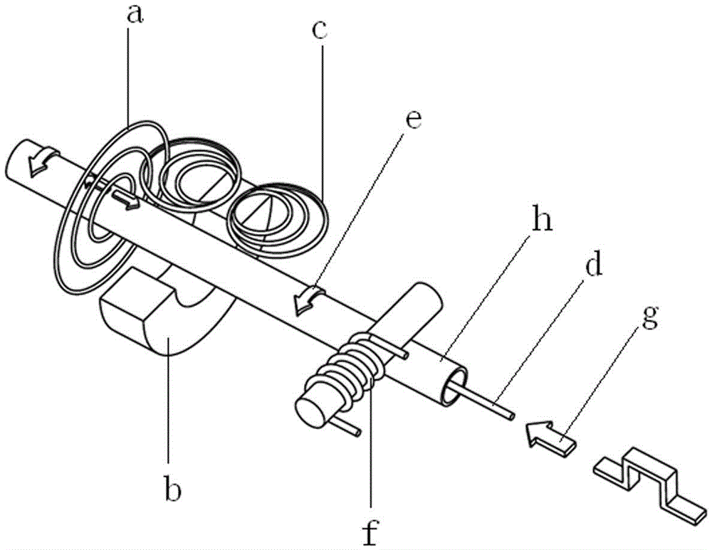
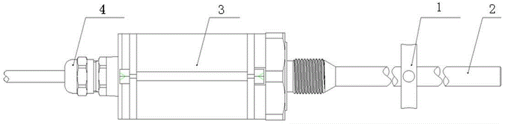
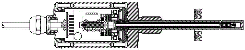
[0023] A magnetostrictive displacement sensor, including a position magnetic ring 1, a measuring rod 2, an electronic chamber 3 and a joint 4 (see figure 2 , image 3 ), the measuring rod 2 includes the outer casing end cover 2-1, the outer casing 2-2 and the plastic insulating sleeve 2-3 (see Figure 4 ), the rear end of the waveguide 2-4 is set inside the plastic insulating sleeve 2-3, the outer sleeve 2-2 is set outside the plastic insulating sleeve 2-3, and the end face cover 2-1 of the outer sleeve is set on the waveguide 2-4 and At the end of the outer casing 2-2, the waveguide 2-4 includes a waveguide wire 2-41, the waveguide wire 2-41 is arranged inside the glass fiber tube 2-45, and the outside of the glass fiber tube 2-45 is provided with a high temperature wire 2-46 , the glass fiber tube 2-45 and the high-temperature wire 2-46 are placed in the inner casing 2...


PUM


Abstract

The invention provides a magnetostrictive displacement sensor and a tensioning mounting method of a waveguide wire thereof. The sensor comprises a position magnetic ring, a measuring rod, a wire outlet connector and an electronic bin, wherein the measuring rod comprises an outer sleeve pipe end face sealing cover, an outer sleeve pipe and a plastic insulation sleeve, the rear end of a waveguide pipe is arranged in the plastic insulation sleeve, the outer sleeve pipe is arranged outside the plastic insulation sleeve, the outer sleeve pipe end face sealing cover is arranged on the end portion of the waveguide pipe and the end portion of the outer sleeve pipe, the waveguide pipe comprises a waveguide wire which is arranged in a glass fiber pipe, a high-temperature lead is arranged outside the glass fiber pipe, the glass fiber pipe and the high-temperature lead are arranged in an inner sleeve pipe, the waveguide wire and the high-temperature lead are fixed at a rear end hollow rivet, and the front end of the waveguide wire is fixed on a front end hollow rivet. The invention further provides the tensioning mounting method of the waveguide wire. The waveguide wire in the waveguide pipe is in a tensioned state all the time, the bending degree is small, the straight degree is high, a clamping ring does not need to be supported by an external device, attenuation of torsional stress wave strength is small, product debugging time is short, measuring precision is high, and work is reliable.

Description

technical field [0001] The invention relates to a tensioning installation method of a magnetostrictive displacement sensor and a waveguide wire thereof. Background technique [0002] The magnetostrictive displacement sensor uses the principle of magnetostriction to accurately measure the position by generating a torsional stress wave pulse signal through the intersection of two different magnetic fields. The measuring element is a waveguide, and the waveguide wire inside the waveguide is made of special magnetostrictive material. The measurement process is generated by the current pulse in the electronic chamber of the sensor, and the current pulse is transmitted in the waveguide wire, thereby generating a circular magnetic field outside the waveguide wire. When the magnetic fields intersect, due to the effect of magnetostriction, a torsional stress wave pulse signal will be generated in the waveguide wire. This torsional stress wave pulse signal is transmitted at a fixed s...

Claims


Application Information

Patent Timeline
Patent Type & Authority Patents(China)
IPC IPC(8): G01B7/02
Inventor 李辉瑛李金初董安应奇
Owner FIRSTRATE SENSOR
Why Eureka
Try Eureka