Eureka AIR delivers breakthrough ideas for toughest innovation challenges, trusted by R&D personnel around the world.

Torch combustion system with automatically adjustable sound speed

A torch combustion system and torch combustion technology, applied in the direction of burner, combustion method, combustion type, etc., can solve the problems of manual adjustment, inability to automatically adjust the size of the gas outlet, consumption of a large amount of steam, etc., to reduce radiation, flame rigidity and The effect of improving combustion, reducing complexity

Active Publication Date: 2014-01-01
JIANGSU SUNPOWER TECH
View PDF9 Cites 9 Cited by
  • Summary
  • Abstract
  • Description
  • Claims
  • Application Information

AI Technical Summary

Problems solved by technology

[0005] The purpose of the present invention is to design a system that can automatically adjust the size of the gas outlet according to the pressure of the flare gas to solve the problems that the existing elevated flare system needs to be manually adjusted to achieve the best combustion effect and consume a large amount of steam. Sonic automatic adjustable torch combustion system with gas outlet size

Method used


Image

  • Torch combustion system with automatically adjustable sound speed
  • Torch combustion system with automatically adjustable sound speed
  • Torch combustion system with automatically adjustable sound speed

Examples


Embodiment 1

[0024] Such as Figure 1-4 shown.

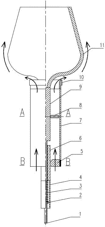
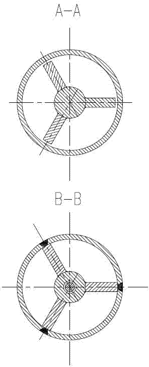
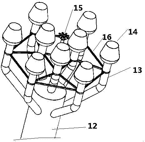
[0025] A torch combustion system with automatic adjustable speed of sound, which includes a torch burner 14, a torch main pipe 12, a torch branch pipe 13, a plum blossom-shaped flame stabilizer 15, and a vibration damping bracket 16. The torch burner 14 is installed on the torch branch pipe 13, and the torch branch pipe 13 and the air inlet of quincunx-shaped flame stabilizer 15 are all linked to each other with torch main pipe 12, and each torch branch pipe 13 is connected into an integral structure by damping support 16, as image 3 As shown, the layout of each torch branch pipe 13 on the torch main pipe 12 is in addition to color and image 3 In addition to the form, you can also use Figure 4 The two common forms shown in . And the structure of each flare burner 14 is as figure 1 As shown, it includes a wind deflector 11, an external sleeve 7 and a support rod 9, the wind deflector 11 can adopt a conta body structure composed of mult...

Embodiment 2

[0030] Such as Figure 5-7 shown.

[0031] Figure 5 It is an optional embodiment of the present invention for ground flares. It includes ground flare main pipe 17, ground flare branch pipe 18 and flare burner 14. During the working process, the outlet area of ​​the flare gas is adjusted by the interaction between the flare gas pressure and the spring to achieve the optimal combustion effect under 100% design conditions, which can replace the ground flare subsystem and achieve the purpose of automatic adjustment. Figure 6 , 7 With Figure 5 The layout of the equivalent flare main pipe 17 and the ground flare branch pipe 18 is the same as that of the first embodiment.


PUM


Abstract

The invention discloses a torch combustion system with automatically adjustable sound speed. The torch combustion system comprises a torch combustor (14), a torch header pipe (12), torch branch pipes (13), a quincuncial flame holder (15) and a vibration attenuation support (16), wherein the torch combustor (14) is installed on the torch branch pipes (13), air inlets of the torch branch pipes (13) are all connected with the torch header pipe (12), the quincuncial flame holder (15) and the torch branch pipes (13) are connected to form an integral structure through the vibration attenuation support (16). The torch combustion system is characterized in that the torch combustor (14) comprises a flow guide cover (11), an external sleeve (7) and a supporting bar (9), the flow guide cover is installed at the upper end of the supporting bar, the external sleeve is sleeved on the supporting bar, and the lower end of the supporting bar is connected with a device for automatically adjusting the height of the flow guide cover (11). According to the torch combustion system, the structure is simple, the size of an air outlet can be automatically adjusted according to the pressure of flare gas, the combustion effect can be obviously improved and the combustion efficiency is high.

Description

technical field [0001] The invention relates to a large-scale torch combustion system, especially a large-scale torch system with a relatively large range of operating conditions, high requirements for radiation and smoke-free radiation, a relatively high pressure of the torch gas and a large amount of liquid, specifically a large-scale torch system Sonic automatic adjustable torch combustion system. Background technique [0002] For the traditional elevated flare system, no matter it is a single-head or multi-head elevated flare, the flare gas outlet area of ​​the flare head is designed to be fixed according to the design conditions. The pressure and flow rate of the flare gas are all different, and they have to be maintained for a long time. The above conditions are outside the scope of the design conditions. The radiation and pollution exceed the standard, and at the same time, it will cause carbon deposits in the flare tip, especially when dealing with heavy component f...

Claims


Application Information

Patent Timeline
Patent Type & Authority Applications(China)
IPC IPC(8): F23D14/46F23D14/64F23G7/06F23N5/00
Inventor 郭宏新何松刘丰赵志红李奇李逸峰余晓燕
Owner JIANGSU SUNPOWER TECH
Why Eureka
Eureka Blog
Learn More