
Oxygen supply system for engine reusing test

A technology for supplying systems and engines, applied in the field of aerospace engines, can solve problems such as test hazards, operator safety threats, waste of low-pressure oxygen, etc., to ensure safety, prevent low control accuracy, and improve utilization.

Inactive Publication Date: 2014-01-01
BEIHANG UNIV
View PDF6 Cites 14 Cited by
  • Summary
  • Abstract
  • Description
  • Claims
  • Application Information

AI Technical Summary

Problems solved by technology

During the engine test, the supply of oxygen is maintained at a high pressure state. At this time, oxygen has strong oxidizing properties. During the high-speed flow process, it is easy to rub against oil stains and esters in the pipeline and spontaneously ignite, resulting in test hazards. Therefore, the oxygen supply system has become a difficult point in the overall system design of the test.
[0003] At present, in the process of designing the oxygen test system in China, some oxygen cylinders are directly used to supply gas to the high-pressure oxygen storage tank, because there are relatively high restrictions on the flow rate of high-pressure oxygen (for details, please refer to the "Oxygen Station Design Specification" GB50030 -2007), such a direct supply method is prone to danger and waste of low-pressure oxygen
For the adjustment of the pressure reducer in the main supply pipeline of the test system, the current common practice is to place the pressure reducer directly in the gas distribution table, and manually adjust the outlet pressure value of the pressure reducer. Work, which caused the direct contact between the personnel and the test working medium, and formed a certain threat to the safety of the operators.

Method used


Image

  • Oxygen supply system for engine reusing test

Examples


Embodiment Construction

[0048] The present invention will be further described in detail below with reference to the drawings and embodiments.

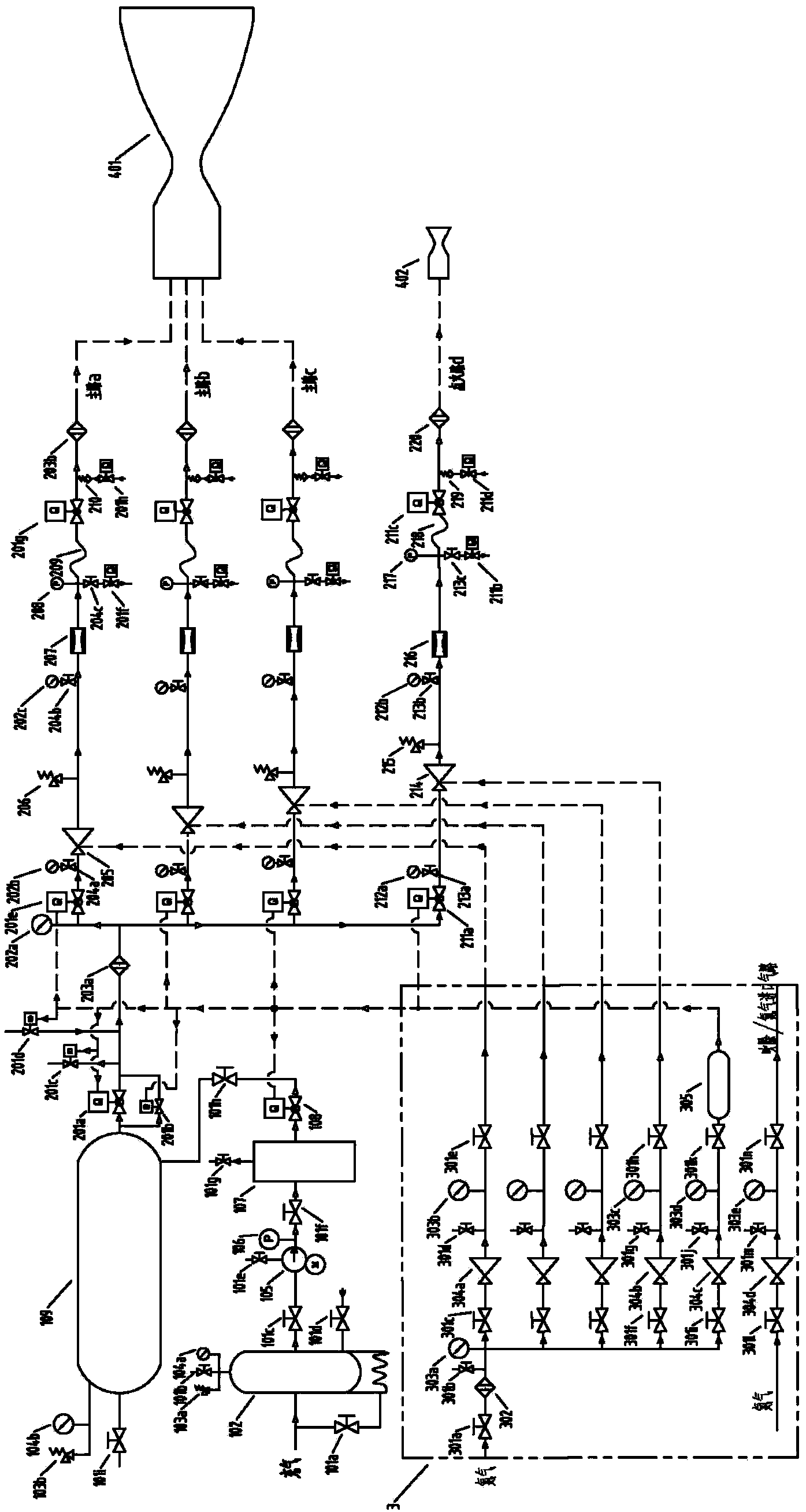
[0049] An oxygen supply system for repeated use of engine tests, such as figure 1 As shown, it includes an oxygen source system, an oxygen transport system, and a gas distribution table 3.

[0050] The oxygen source system includes manual shut-off valve (101a~101h), low pressure liquid oxygen storage tank 102, safety valve (103a, 103b), pressure gauge (104a, 104b), liquid oxygen pump 105, pressure sensor 106, vaporizer 107, pneumatic shutoff Valve 108, high-pressure oxygen storage tank 109 and pipelines.

[0051] The input of the low-pressure liquid oxygen storage tank 102 is connected to the inflation pipeline. The bypass of the inflation pipeline is provided with a manual shut-off valve 101a. The top of the low-pressure liquid oxygen storage tank 102 is connected to a safety valve 103a, a manual shut-off valve 101b, and a pressure gauge through a three-way conne...


PUM


Abstract

The invention discloses an oxygen supply system for an engine reusing test. The oxygen supply system comprises an oxygen source system, an oxygen transporting system and an oxygen distribution table. In the oxygen source system, a process of preparing oxygen through a liquid oxygen vaporization method is adopted, and the utilization rate of raw liquid oxygen materials is improved. Through the real-time monitoring of a pressure sensor, the whole process can be safely performed. In the oxygen transporting system, measures are taken for control over the flow speed of an oxygen pipeline, a mode of connecting two pneumatic cutoff valves in parallel is adopted, and a small-aperture pneumatic cutoff valve is turned on in advance to be served as a pilot valve. The pressures of two ends of a large-aperture pneumatic cutoff valve are balanced, and the large-aperture pneumatic cutoff valve is turned on, so that a good effect of reducing the flow speed of high-pressure oxygen can be achieved. In the oxygen transporting system, a scheme of three main paths and an ignition path is adopted. A pipeline assembly can be reasonably selected according to test requirements.

Description

Technical field [0001] The invention relates to an oxygen supply system for liquid rocket engine testing, which belongs to the technical field of aerospace engines. Specifically, it is an oxygen supply system with high safety factor, high control precision, and remote control performance. Background technique [0002] At present, in the field of repeated use of aerospace engine tests, the supply system is required to be able to supply propellant multiple times for a long time. The realization of the propellant supply system is the guarantee for the successful engine test, and the design of the oxidant supply system is an important content. As a common oxidant, oxygen occupies an important position in the field of engine propellants. During the engine test, the oxygen supply is maintained at a high pressure. At this time, the oxygen has strong oxidizing properties. In the process of high-speed flow, it is easy to rub against the oil and ester substances in the pipeline and ignite...

Claims


Application Information

Patent Timeline
IPC IPC(8): F17C7/04F17C13/02F17C13/04F17D1/02G01M15/02
Inventor 俞南嘉戴健蔡国飙
Owner BEIHANG UNIV
Learn More