
A raking device for coal mining shield support

A technology of shielding support and rake transportation, which is applied in mine roof support, mining equipment, earthwork drilling and mining, etc. It can solve the problems of low production efficiency, high labor intensity of workers, and harsh production and working environment, so as to reduce the labor cost of enterprises and change Heavy physical labor, the effect of improving production safety

Active Publication Date: 2016-04-27
BEIJING CHENGTIAN HENGYE COAL MINE EQUIP CO LTD
View PDF7 Cites 0 Cited by
  • Summary
  • Abstract
  • Description
  • Claims
  • Application Information

AI Technical Summary

Problems solved by technology

However, there is still a functional defect in this bracket, that is, the bracket itself only has the function of supporting the roof and ensuring the safety of the stope space; and the coal falling and coal transportation for mining have to be completed by manual blasting and manual shipment.
The disadvantages of this production process are: the labor intensity of workers is high, the working environment is poor, and the dust is large. Because it is the way of blasting and dropping coal, in addition to the problems of large number of workers and high labor intensity of workers, it also increases the possibility of blasting accidents. hidden dangers, etc.
[0006] The above-mentioned new blasting coal mining technology in the coal mining face still has the following defects: because it is the way of blasting and dropping coal, in addition to the problems of large number of workers and high labor intensity of workers, it also increases the possibility of blasting. risk of accidents, etc.
The working environment is poor and there is a lot of dust, especially in the coal loading process. The blasting coal is completely loaded into the conveyor with a shovel manually. The production efficiency is extremely low, the labor intensity of the workers is very high, and the labor environment is relatively harsh.

Method used


Image

  • A raking device for coal mining shield support
  • A raking device for coal mining shield support
  • A raking device for coal mining shield support

Examples


Embodiment Construction

[0022] The preferred embodiments of the present invention will be described below in conjunction with the accompanying drawings. It should be understood that the preferred embodiments described here are only used to illustrate and explain the present invention, and are not intended to limit the present invention.

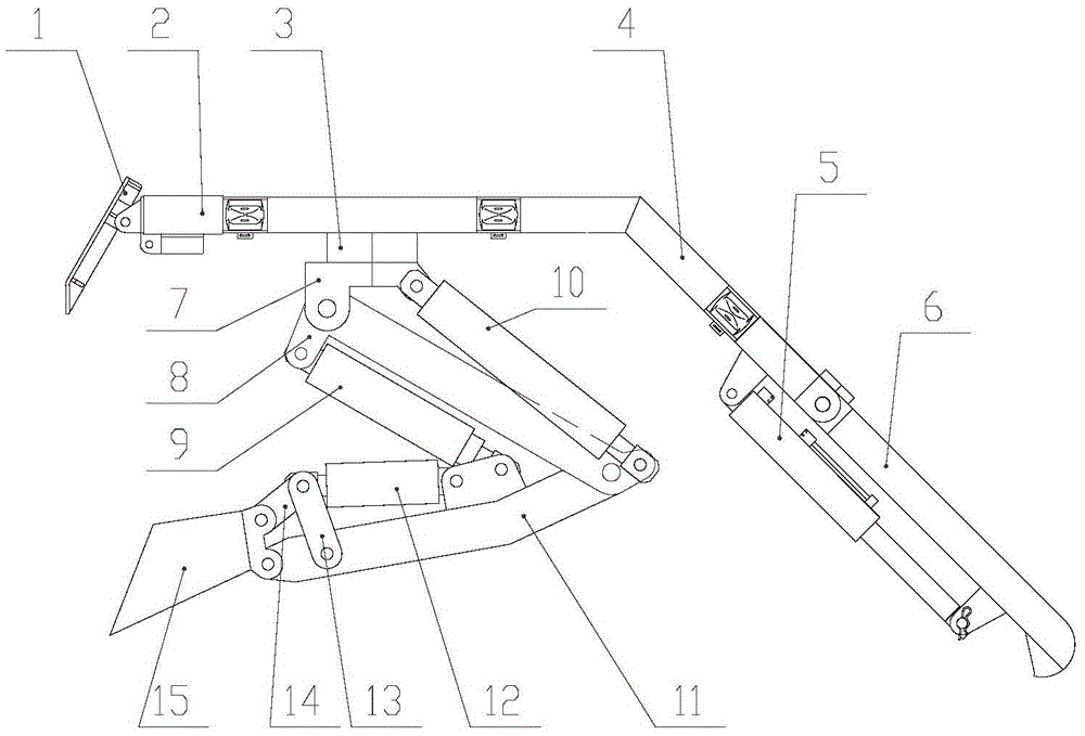
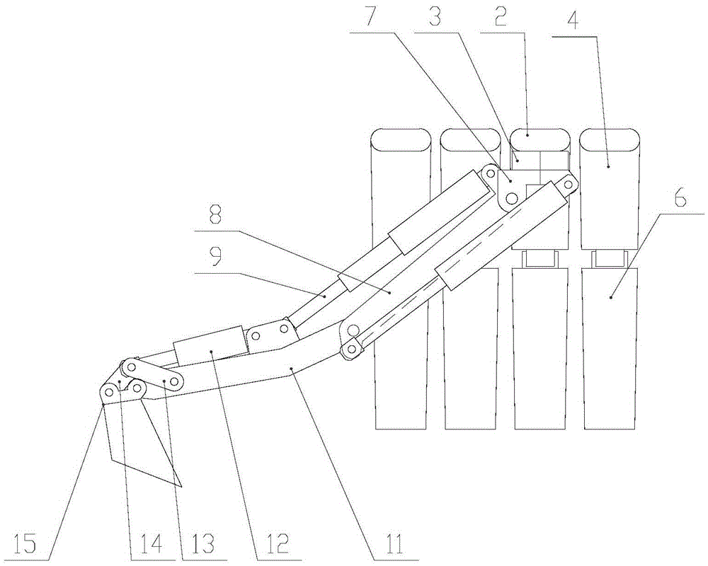
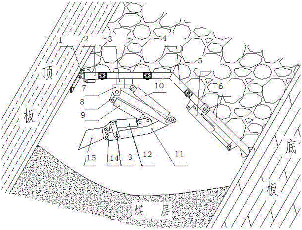
[0023] figure 1 As shown, a structural schematic diagram of a raking device for a coal mining cover support, including: a guide beam 1, a top beam 2, a fixed seat 3, a cover beam 4, a tail beam jack 5, a tail beam 6, a rotating frame 7, and a primary arm 8 , Secondary arm jack 9, primary arm jack 10, secondary arm 11, rake transport bucket jack 12, secondary arm connecting rod 13, rake transport bucket connecting rod 14, rake transport bucket 15. The guide beam 1 is connected with the top beam 2, the top beam 2 is connected with the fixed seat 3 and the cover beam 4 respectively, the cover beam 4 is connected with the tail beam 6 and the tail beam jack 5 respectivel...


PUM


Abstract

The invention relates to a raking device of a coal mining shielding support. The raking device comprises a guide beam, a top beam, a fixing base, a shielding beam, a tail beam jack, a tail beam, a rotary frame, a first-level arm, a first-level jack, a second-level arm, a second-level jack, a second-level arm connecting rod, a raking hopper, a raking hopper jack and a racking hopper connecting rod. The raking device has the advantages that by means of raking motions of the raking device, coal is peeled from coal mass, and particularly, coal can be loosened and raked off on a work face in any direction within 360 degrees; the coal which is raked off is pushed into a coal handling chute, so that the coal is transported to the outside; manual drilling blasting for coal raking is needless, and production safety is improved; heavy manual labor of manual coal raking is changed, labor cost of an enterprise is reduced, and production efficiency and work environment of workers are improved; the recovery rate of coal is improved and the exploiting life limit of a coal mine is prolonged.

Description

technical field [0001] The invention relates to a coal mining device, in particular to a raking device for a coal mining shield support. Background technique [0002] At present, the production processes adopted by coal mines in China and abroad are basically divided into two categories: one is the use of coal shearers, which are responsible for spiral cutting and coal loading, and scraper conveyors are responsible for coal transportation and hydraulic supports are responsible for Supporting the roof, that is, three-machine supporting combined coal mining, this production process is referred to as machine mining. The advantages of the machine mining process are: high production efficiency and good safety performance. [0003] Another production process is to mine coal by blasting and dropping coal, which is called blast mining for short. The advantage of blast mining technology over mechanical mining technology is that it has lower requirements on coal seam occurrence cond...

Claims


Application Information

Patent Timeline
Patent Type & Authority Patents(China)
IPC IPC(8): E21D23/04E21C27/18
Inventor 王洪英陈志才徐兴强石洪起舒文利王昱
Owner BEIJING CHENGTIAN HENGYE COAL MINE EQUIP CO LTD
Learn More