A single-phase grounding protection method for distribution network based on transient power direction
A single-phase grounding, transient power technology, used in emergency protection circuit devices, emergency protection circuit devices, electrical components, etc. for limiting overcurrent/overvoltage Grounding protection principle The zero sequence current is small, and the current flow direction is difficult to distinguish, etc., to achieve the effect of high reliability
- Summary
- Abstract
- Description
- Claims
- Application Information
AI Technical Summary
Problems solved by technology
Method used
Image
Examples
Embodiment 1
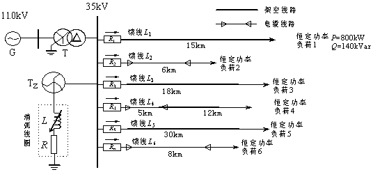
[0035] Embodiment 1: as figure 2 Shown is a 35kV distribution network composed of 6 feeder lines whose neutral point is grounded through an arc suppression coil. G in this network is an infinite power supply; T is the main transformer with a transformation ratio of 110kV / 35kV and a connection group of YN / d11; the distribution voltage side of the main transformer in my country's distribution network is generally a delta connection, and there is no neutral point in the system. When the system adopts the resonance grounding method, it is necessary to obtain a neutral point that can be grounded by the arc suppression coil. Adding a grounding transformer is the best solution. The best way, here T Z It is a zigzag transformer specially used for grounding of the compensation grid; L is the arc suppression coil, and R is the damping resistance of the arc suppression coil. The line adopts three types of lines: overhead line, overhead line-cable hybrid line and cable line. The numbers ...
Embodiment 2
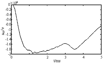
[0040] Embodiment 2: as figure 2 In the distribution network system shown in which the neutral point is grounded through the arc suppression coil, the system parameters are the same as those in Embodiment 1. Now assume the feeder L 2 A single-phase ground fault occurs in phase A at a distance of 4km from the busbar. The initial phase angle of the fault is 90°, the fault transition resistance is 20Ω, and the sampling frequency is 10kHz. The waveform diagram of the zero-sequence voltage of the bus in the window at 5ms after the fault is as follows Figure 10 Shown; feeder L 1 , L 2 , L 3 … L 6 The zero-sequence current waveform is shown in Figure 11-16 shown. Intercept the zero-sequence voltage of the busbar and the zero-sequence current value of each feeder in the 1ms time window after the fault, and calculate the transient zero-sequence power value of each feeder according to formula (1):
[0041] S ( j )=[2.00×10 5 -1.40×10 8 1.27×10 6 2.22×10 5 1.03×10 ...
PUM
 Abstract
Description
Claims
Application Information
 - R&D
- Intellectual Property
- Life Sciences
- Materials
- Tech Scout
- Unparalleled Data Quality
- Higher Quality Content
- 60% Fewer Hallucinations
Browse by: Latest US Patents, China's latest patents, Technical Efficacy Thesaurus, Application Domain, Technology Topic, Popular Technical Reports.
© 2025 PatSnap. All rights reserved.Legal|Privacy policy|Modern Slavery Act Transparency Statement|Sitemap|About US| Contact US: help@patsnap.com


