Transformer Partial Discharge UHF Locating Analyzer and Its Locating Analysis Method
A partial discharge and analysis method technology, applied in the direction of testing the dielectric strength, etc., can solve the problems of not being able to obtain the specific location of the transformer fault point, inconvenient maintenance of the transformer, and difficult to locate the circuit to lock the distance between the discharge source and the UHF sensor, etc., to achieve isolation Good noise effect, improved stability factor, easy to use
- Summary
- Abstract
- Description
- Claims
- Application Information
AI Technical Summary
Problems solved by technology
Method used
Image

Examples
Embodiment 1
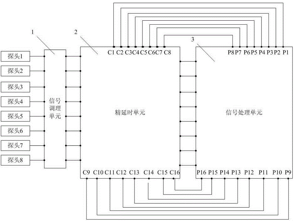
[0037] Such as figure 1 As shown, the transformer partial discharge UHF positioning analyzer of this embodiment includes a signal conditioning unit 1 for receiving the discharge signal collected by the probe and conditioning the received discharge signal, and a signal processing unit 3 for calculating the discharge distance , the fine delay unit 2 that delays the discharge signal after conditioning, the above fine delay unit 2 is also connected with the signal processing unit 3, and sends the delayed signal to the signal processing unit 3 and the receiving signal processing unit 3 Delay control signal.
[0038] Wherein, the signal conditioning unit 1 includes at least 4 independent signal conditioning modules; the above-mentioned fine delay unit 2 includes at least one independent fine delay module; the above-mentioned signal processing unit 3 includes at least one set of independent delay signal output ports and road signal Input interface; the number of the above-mentioned ...
Embodiment 2
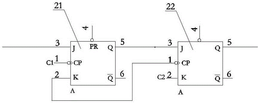
[0040] Such as figure 2 as shown, figure 2 It is the circuit schematic diagram of the fine delay module. On the basis of Embodiment 1, each group of delay signal output ports in this embodiment includes a first delay signal output pin and a second delay signal output pin; the above-mentioned fine delay module is composed of the first JK flip-flop 21 and the second JK flip-flop 22 are connected to form; the J input end of the first JK flip-flop 21 is connected to the signal conditioning module, the Q output end is connected to the J input end of the second JK flip-flop 22, and the CP input end is connected to the delay signal The first delayed signal output pin of the output port is connected; the Q output terminal of the above-mentioned second JK flip-flop 22 is connected with the signal processing unit 3, and the K input terminal is connected with the second delayed signal output pin of the delayed signal output port , the CP terminal of the second JK flip-flop 22 is conn...
Embodiment 3
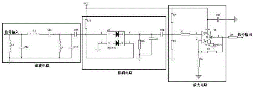
[0042] image 3 It is a schematic circuit diagram of a signal conditioning module. On the basis of Embodiment 1 or 2, the signal conditioning module includes a filter circuit, an isolation circuit, and an amplifier circuit connected in sequence. The above filter circuit is a third-order filter circuit with a passband of 400M to 700M. The circuit specifically includes inductor L2, inductor L3, inductor L4, capacitor C14, capacitor C15, capacitor C16, and capacitor C26. Among them: inductor L2, inductor L3, capacitor One end of C14 is connected to the input signal; the other end of inductor L2 and capacitor C14 is grounded; the inductor L3, capacitor C15, and capacitor C26 are connected in series; the inductor L4 and capacitor C16 are connected in parallel, and one end is connected between capacitor C15 and capacitor C26, and the other end is grounded ; The capacitor C14, capacitor C15, and capacitor C16 are non-inductive capacitors of 100 pF, and the inductor L2, inductor L3, a...
PUM
 Abstract
Description
Claims
Application Information
 - R&D
- Intellectual Property
- Life Sciences
- Materials
- Tech Scout
- Unparalleled Data Quality
- Higher Quality Content
- 60% Fewer Hallucinations
Browse by: Latest US Patents, China's latest patents, Technical Efficacy Thesaurus, Application Domain, Technology Topic, Popular Technical Reports.
© 2025 PatSnap. All rights reserved.Legal|Privacy policy|Modern Slavery Act Transparency Statement|Sitemap|About US| Contact US: help@patsnap.com